Note: this is the first part of three articles about my experience building a 1980s Yugoslav 8-bit computer called the Galaksija. This part is mostly focused on the technical aspects of building this computer. Part II will focus on the history and the cultural impact of this machine. A BCS version of this article was published on RetroInfo. It is largely based on my sprawling Twitter thread about the Galaksija.
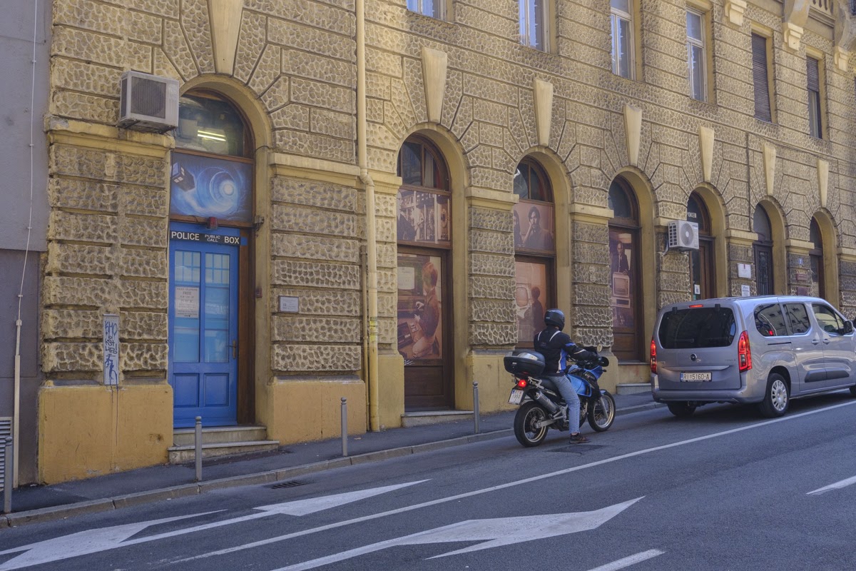
At the start of the coronavirus pandemic, I unexpectedly took up an old hobby of mine – repairing old electronics. It started in April, with an older, but still relatively modern Macbook. Soon I tackled a 1993 IBM Model M keyboard, and then around the end of summer I attempted my first serious retro build: the original Galaksija 8-bit Yugoslav microcomputer, designed by Voja Antonić in 1983. It was all thanks to my first visit to the PEEK&POKE computer museum in Rijeka, Croatia.
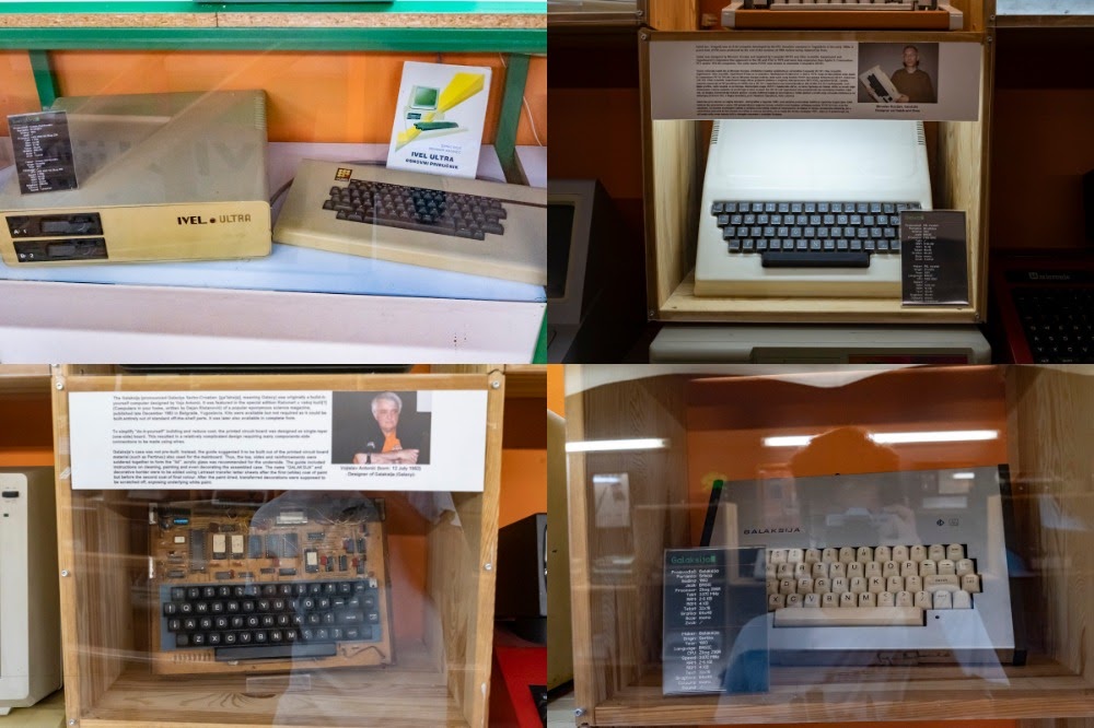
I was completely amazed by this museum, but despite the extensive collection on the ground floor which includes the IBM PC, Macs of all types, Apple IIs and NeXT workstations, I got the most excited when I climbed to the second floor and discovered all the domestic, Yugoslav built computers. Growing up in the 90s and the early 2000s, I never got to experience the period of 8-bit microcomputers, and in school I never learned about domestic computers like the Galeb, Orao or Galaksija. It was so exciting to see them all in one spot, so this visit inspired me to research this topic more. As I started learning more about this period, I came across a number of fantastic projects, like Josip Perušanec’s Orao and Galeb emulators and Orao and Galaksija clones. Tomaž Kac’s website was amazing: hundreds of old Yugoslav computer magazine scans, including program listings, schematics and other stories from the 80s. I made a decision: in order to better understand this old technology, but also the tech culture which is still relevant, I will build one of these computers from scratch.
Thanks to lots of available documentation and the fact that it was originally designed for DIY, I decided to build a Galaksija. Right around this time a crowdfunding campaign was started to fund a documentary film about Galaksija. The campaign also included an option to order a new DIY kit. I thought about ordering one, but I decided to construct it on my own: the kits are scheduled for delivery in 2021 and I wanted to get started right away. Nonetheless, I still supported the crowdfunding effort and I’m looking forward to seeing the movie some time next year! This ended up increasing my cost somewhat, since I ended up ordering quite a few wrong parts that had to be replaced, but I like to think that this helped me learn more! Regardless, I truly enjoyed the process of building a Galaksija, and I’m excited to share my story.
Just like all my projects, I primarily documented it on Twitter. I started with a few self imposed rules:
- I will try to use the original or identical parts as you would in the 80s
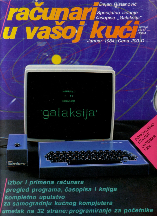
- I will primarily used the original DIY guide from the first issue of Računari u vašoj kući magazine (full magazine scan available at retrospec.sgn.net). I will use other sources only if absolutely necessary.
- I will build the original Galaksija with 8KB of ROM (ROMs A and B) and 6KB of static memory
- I won’t build my own power adapter, instead I’ll use an off the shelf 5V/2A (the original guide included instructions on building your own)
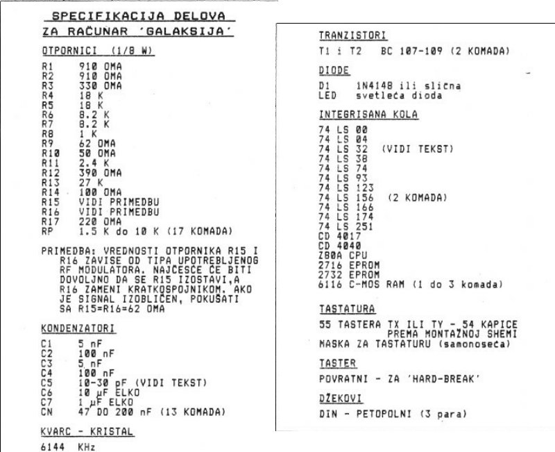
I started by making a spreadsheet and finding equivalent parts to those listed on page 54 of Računari u vašoj kući issue 1.
I managed to find most parts on Mouser Electronics. There were a few exceptions:
- 2 x 2732 EPROM and 1 x 2716 EPROM: got them on eBay (I ended up getting two pairs of 2732 due to issues with my EPROM programmer)
- 6116 RAM: I originally got it on Mouser, but it was the wrong width. I got replacements on eBay
- Z80A CPU: originally I got a completely wrong CPU on Mouser. Then I got a new old stock 1983 SGS Z80 on eBay
- Keyboard switches: got them on KBDfans
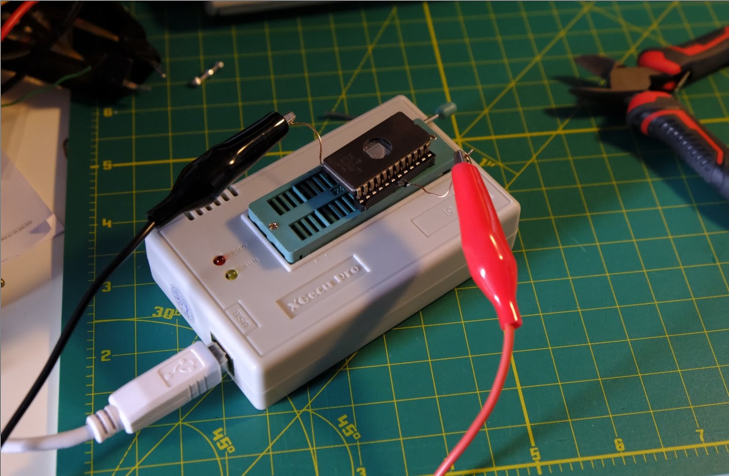
Along with these mandatory components, I got an EPROM programmer and eraser. The programmer I got (LAQIYA TL866Ⅱ Plus) ended up being the worst possible choice, but more on that later.
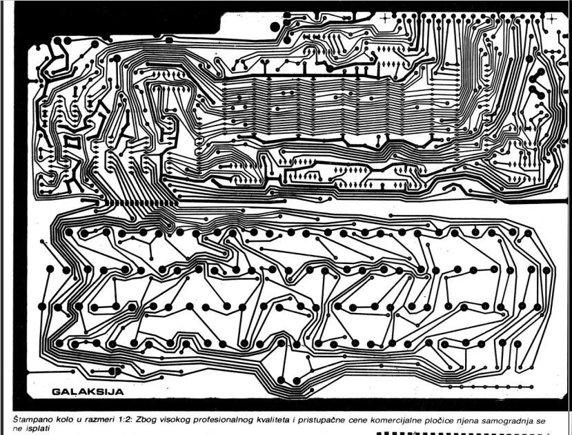
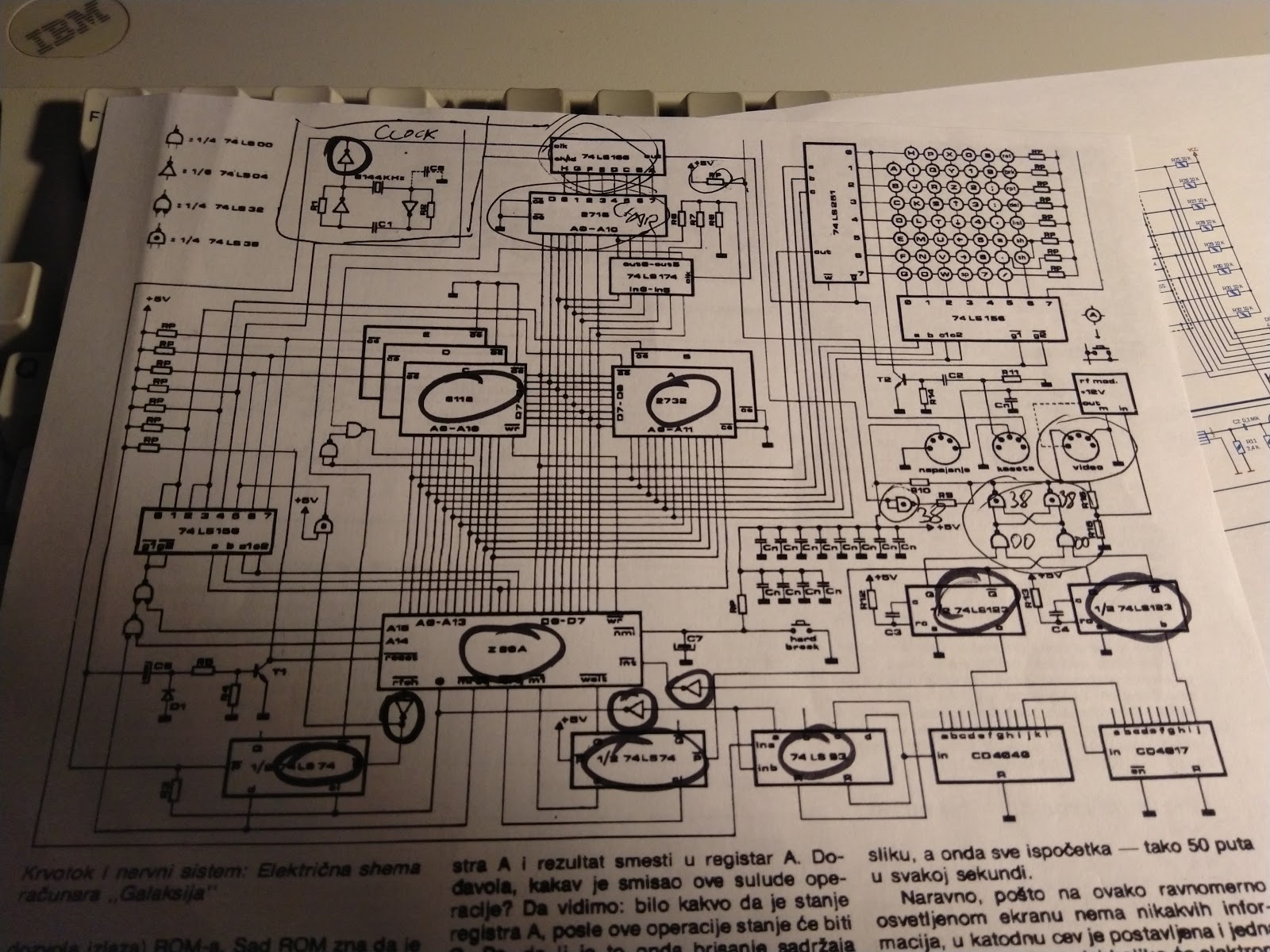
The most important component was the PCB. The schematic was published in Računari, but making a DIY PCB is beyond my current capabilities. Moreover, most DIY Galaksija builders in the 80s got their PCBs through Računari, so I decided to order my PCB as well. Luckily, in 2020 it’s fairly easy and cheap to order a PCB online, and thanks to the great gerber files hosted on spetsialist-mx.ru “Russian Galaksija website”, there was no need to convert the old magazine scan. I got a pretty good price on jlpcb.com, but the minimum order was 5 boards. I decided to get them anyway – I ended up sending 2 to Croatia and one to Macedonia, so eventually we may have 4 new Galaksija from this single order! I used the 5th board to experiment with making a case.
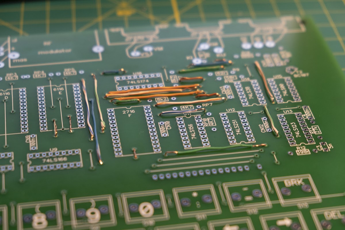
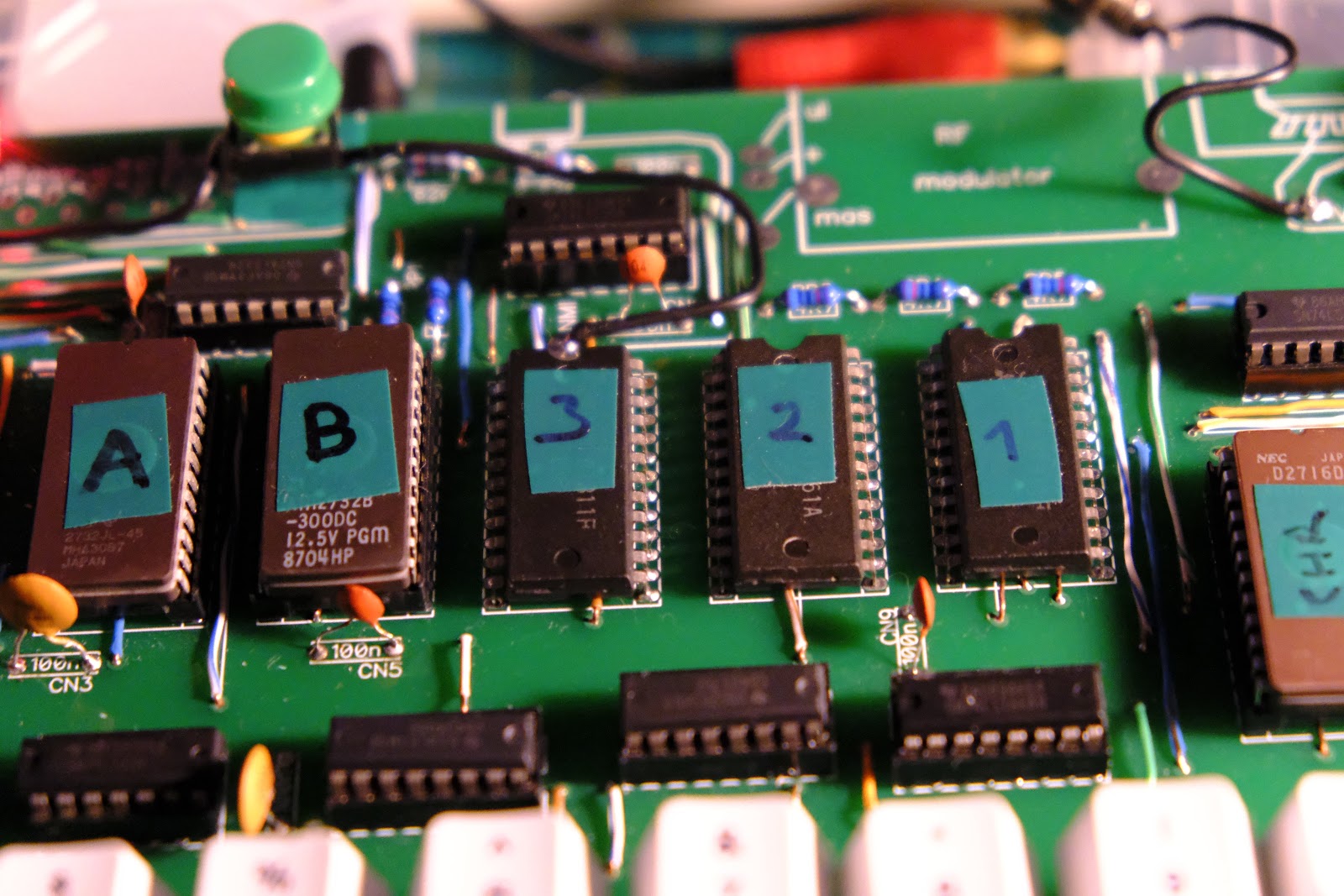
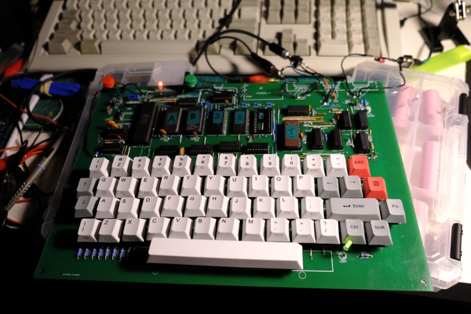
When I got the PCB, I started by soldering 119 jumpers. While reading the guide in Računari I already realized that this was going to be tedious work – if only I took the warning seriously enough! I didn’t count them carefully enough and I missed two crucial ones. I only discovered this later on, but more on this later. I used copper wires from CAT 5 cables, as a sort of an homage to the original guide which suggested using telephone wire. After completing the jumpers, I got started with the IC sockets. I made a few mistakes when ordering these (mainly wrong widths), but I also messed up with bad quality sockets for the memory chips. Once the sockets were in, I soldered the capacitors and resistors. After soldering 117 (!) jumpers, these were a breeze.
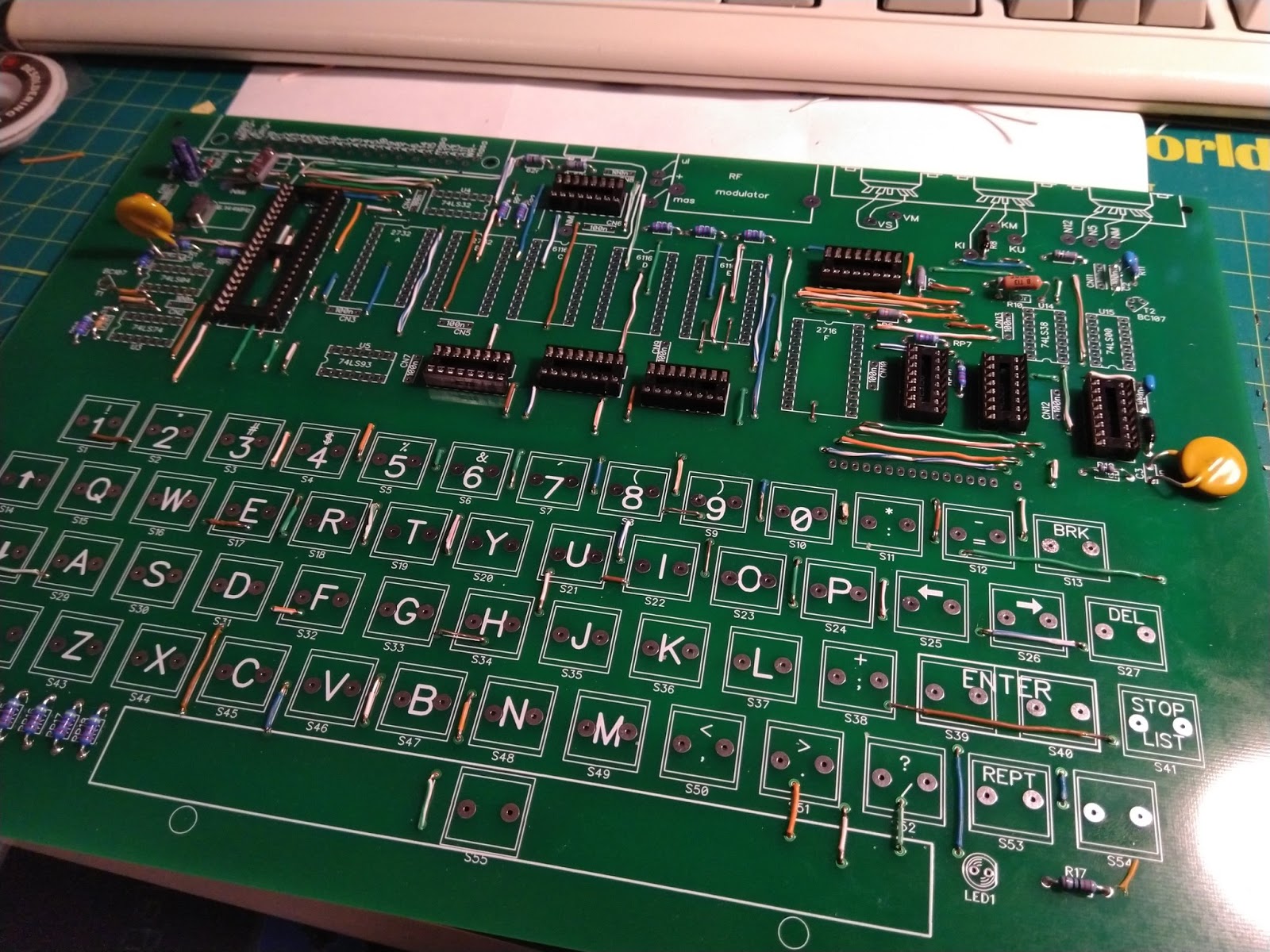
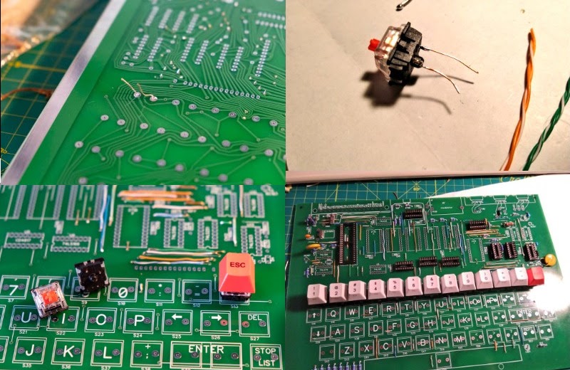
Then I moved onto the keyboard. I had some issues with the key switches too: due to the difference in connector placement on modern key switches vs. the PCB designed for those from the 80s, I couldn’t solder them directly. I ended up adding some extra copper wire in order to make the connections. This sort of worked, but it isn’t ideal. Luckily I don’t have any issues typing, but some keys are a bit unstable. Coincidentally, Voja Antonić, Galaksija’s original designer, just published a new version of the PCB on Hackaday that features new key switch connections, including a few other details (mainly the double layer PCB that doesn’t require jumpers).
Then I got the EPROMs and the EPROM programmer! I had no issues with the 2716 2KB EPROM which is used as a character generator ROM by Galaksija (it stores the graphics to use for character generation). However, my LAQIYA TL866Ⅱ Plus continuously failed to burn the 2732 EPROMs used for ROM A and ROM B. After a lot of trial and error, I realized that the 2732s I got needed to be programmed with 21V, and my programmer tops out at 18. I managed to resolve this by connecting the programming pin to a 21V power supply, but I still couldn’t successfully burn it. At most I could get the first out of every 8 bytes. I won’t go into too much detail here, but you can read the whole story on Twitter.
In the end I destroyed one 2732 and programmed the other one with the help of 32 spreadsheets and 32 separate burn attempts. This way I got ROM A ready, and I got a 2732B EPROM for ROM B. 2732Bs are programmed with 12V, but I still had issues. It turned out 2732s require 50ms programming pulse, which the TL866II Plus again couldn’t deliver. If you’re choosing an EPROM programmer for 2732s steer away from this one. In the end I put together a bash script that successfully programmed the 4KB by attempting the burn approximately 1000 times.
My struggle with EPROMs was incredibly frustrating, but I ended up learning a lot not only about EPROMs but also about the actual ROMs used by Galaksija. I learned the most from the complete ROM A disassembly by Tomaž Šolc. This is an incredible document that I’m still using for research. ROM A features video generation functions (Galaksija uses the CPU to generate the image) and essential BASIC commands. ROM B was released in 1984 as the first Galaksija software upgrade, featuring advanced BASIC functions, assembler, support for the monitoring program, printer support and a few other things. I have the copies of the ROMs and some additional documentation on my GitHub.
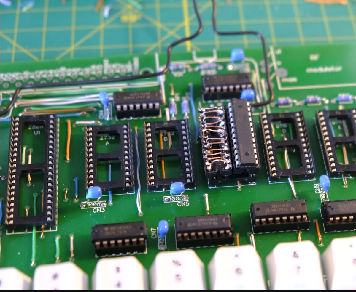
Once ROM A was programmed, I got the 6116 ROM: in half the width! I ended up improvising a horrible looking adapter, but it ended up being useless since the sockets on the board weren’t good enough anyway (I didn’t know this yet). At this point I finally installed the CPU and realized that I didn’t get a Z80A, but a completely random and unrelated 40 pin model. How I managed to make this mistake – I have no idea. I had to go back to eBay.
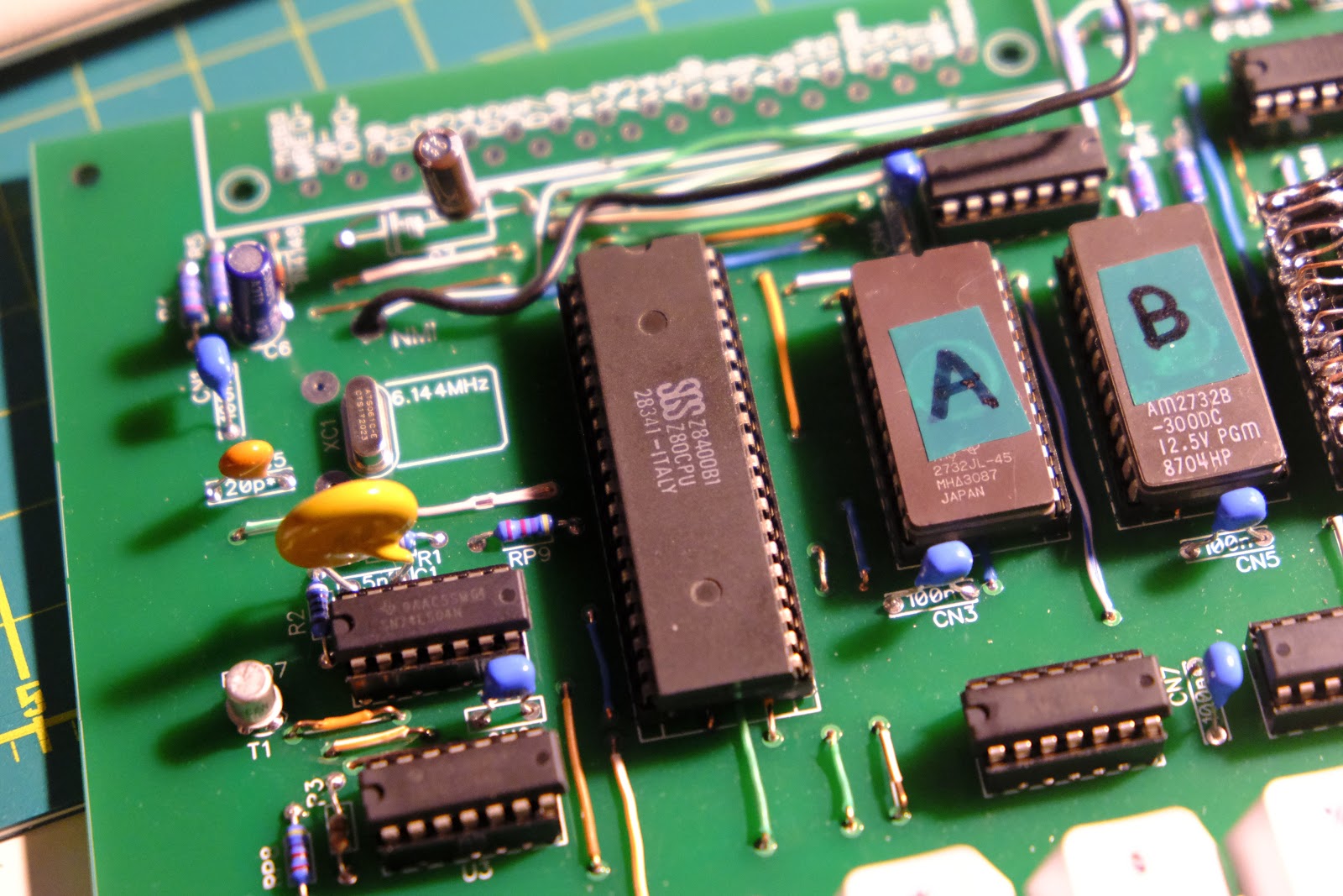
When I got the replacement – an Italian Z80 from 1983 – I got excited hoping I’ll finally get some kind of image on the screen. It just wasn’t meant to be. By using a logic probe I found an issue with the CD4017 decade counter: it turned out it wasn’t a CD4017 at all but CD40175BEE4 flip flop with an almost identical name. I had all these issues due to my lack of experience. I started to fill out my Galaksija schematic with notes as I tried to resolve problems.
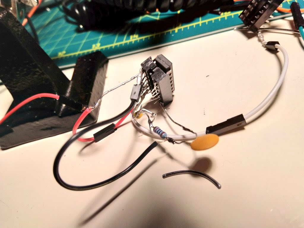
When I finally got the replacement CD4017, I first got excited and then disappointed again. I finally got some kind of image using my RCA/HDMI adapter which I’m using with my modern LCD. I got image synchronization and the adapter switched to PAL, but other than that the image was completely white. I started reading all the articles I could find about image problems with Galaksija. I related to the article “I’ll kill myself, it won’t work” from Računari issue 3… But I had no solution. Since my Z80 is very similar to a CPU Tomaž Šolc found in an old Galaksija which had image generation problems, I convinced myself that I had the same issue. The original owner constructed a small circuit to synchronize the 74LS166 shift register with the CPU. I ended up making the same circuit – with no success getting an image. It didn’t help since I had no issues with CPU timing, but making this circuit helped me better understand how Galaksija generates image, and how analog image works in the first place.
In the meantime I ordered a small oscilloscope (YEAPOOK ADS5012h) and started to analyze the signals between the CPU, ROM and memory. Very quickly I noticed that the WAIT and IORQ lines have no signal. But I still couldn’t figure out why. After a long period of troubleshooting, I tracked it down to two missing jumpers at the top of the board. I felt incredibly silly because in order to find the missing jumpers I spent so much time analyzing the signals instead of just counting the jumpers or simply looking at the board. But still – with the jumpers soldered I finally got some characters on the screen!
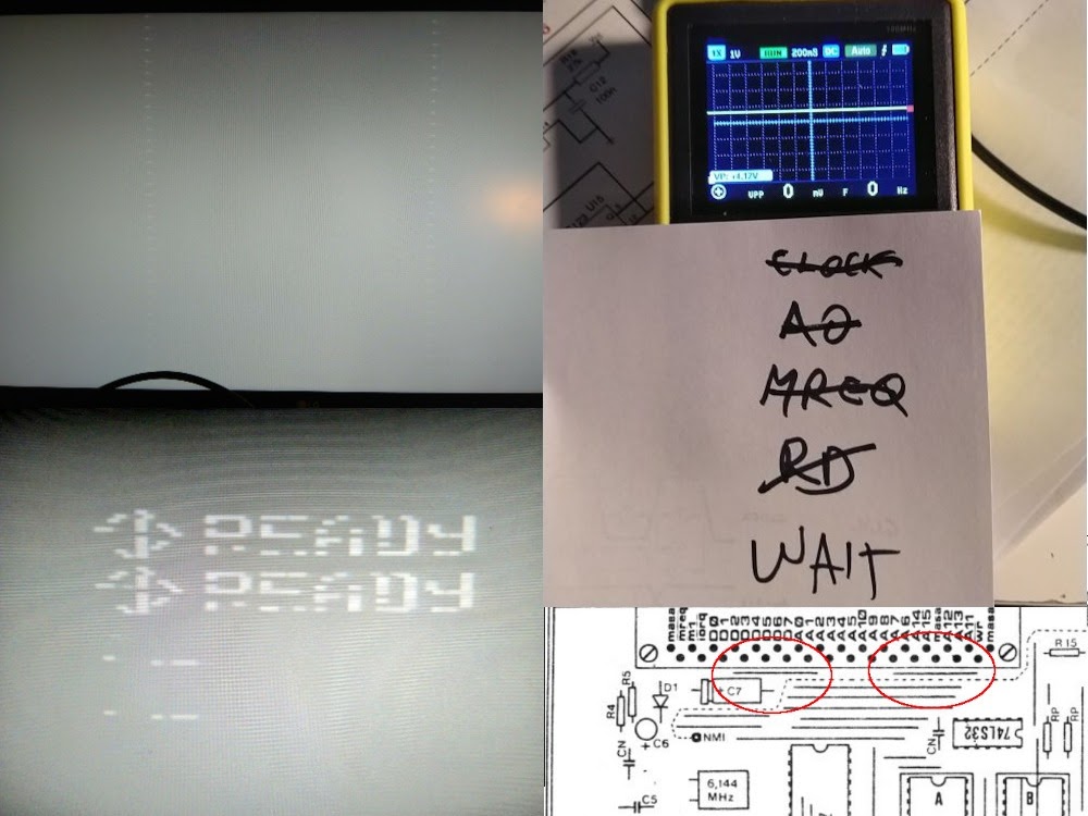
It’s hard to explain how happy I was to see that first READY on the screen! I had double rows, missing pixels and horrible contrast, Galaksija couldn’t run even the simplest PRINT command, but after all the troubles I finally got something on the screen. In terms of fixing image problems, I fixed the contrast and flickering fairly easily – I experimented with resistors R9 and R10, I lowered the overall power supply voltage from 5V to 4.63V, and I connected the RCA/HDMI adapter to the same voltage. However, I still had missing pixels, double rows and I couldn’t run any commands.
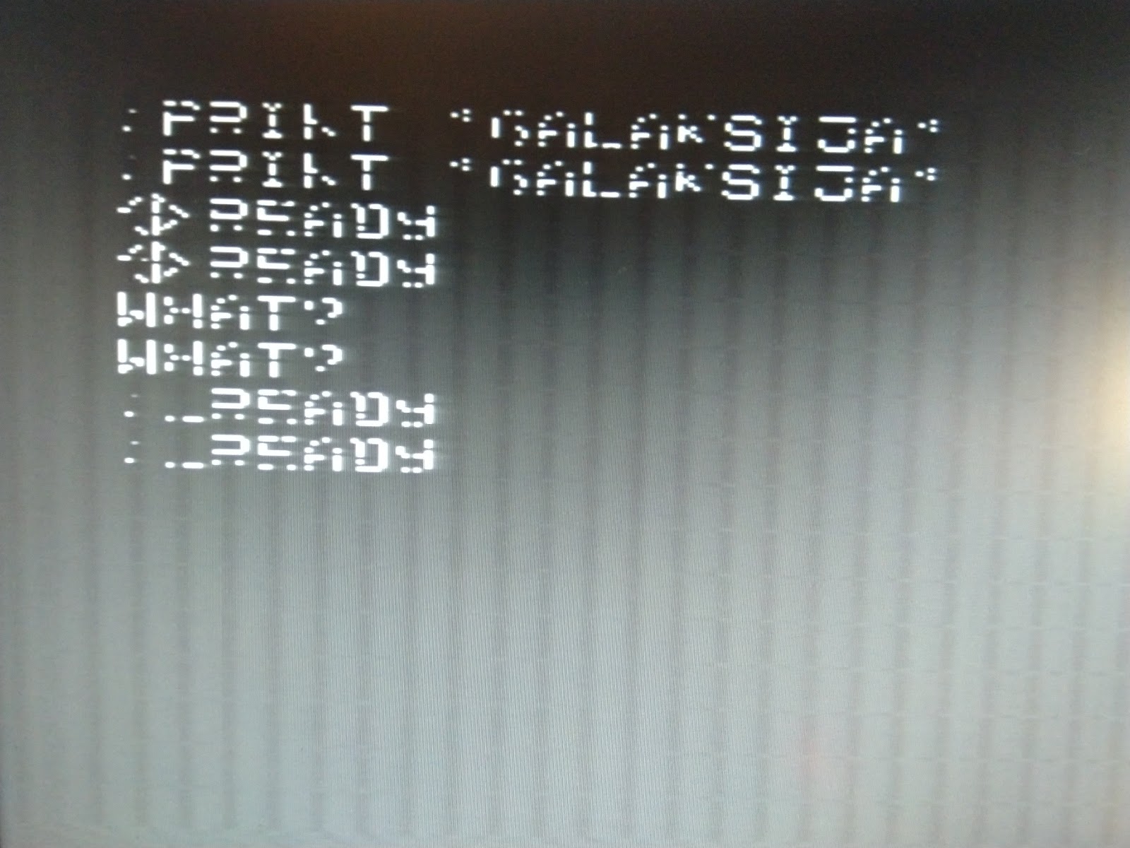
Finally, I accidentally noticed that if I touched the first 6116 memory chip (I got the correct width ones from eBay in the meantime) the image would stabilize. This ended up being my final eureka moment – it turned out that my low quality IC sockets couldn’t provide a good connection between the RAM and the rest of the board. I quickly took out the sockets and soldered the memory directly to the board. I got a clear image and the commands immediately started to work!
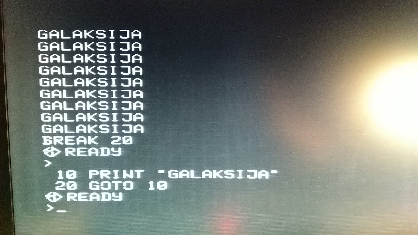
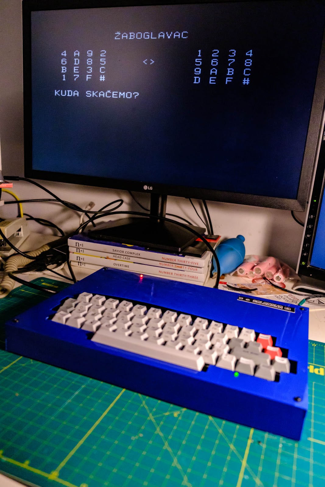
When I finally got Galaksija working, I started to try out programs and games. Tomaž Kac’s website had tons of programs with great documentation. I also found many programs in a wav program dump by Marko Šolajić. I had a great time playing Žaboglavac, a game released by Retroinfo in 2020!
To load programs I used my laptop since I don’t have a tape recorder. At first I had some issues due to sound volume, but once I removed the R14 resistor all the issues went away. Over the next few days I had fun with Galaksija and I tried out more or less every program and game available for download online. I then decided to finish this project with three mini projects:
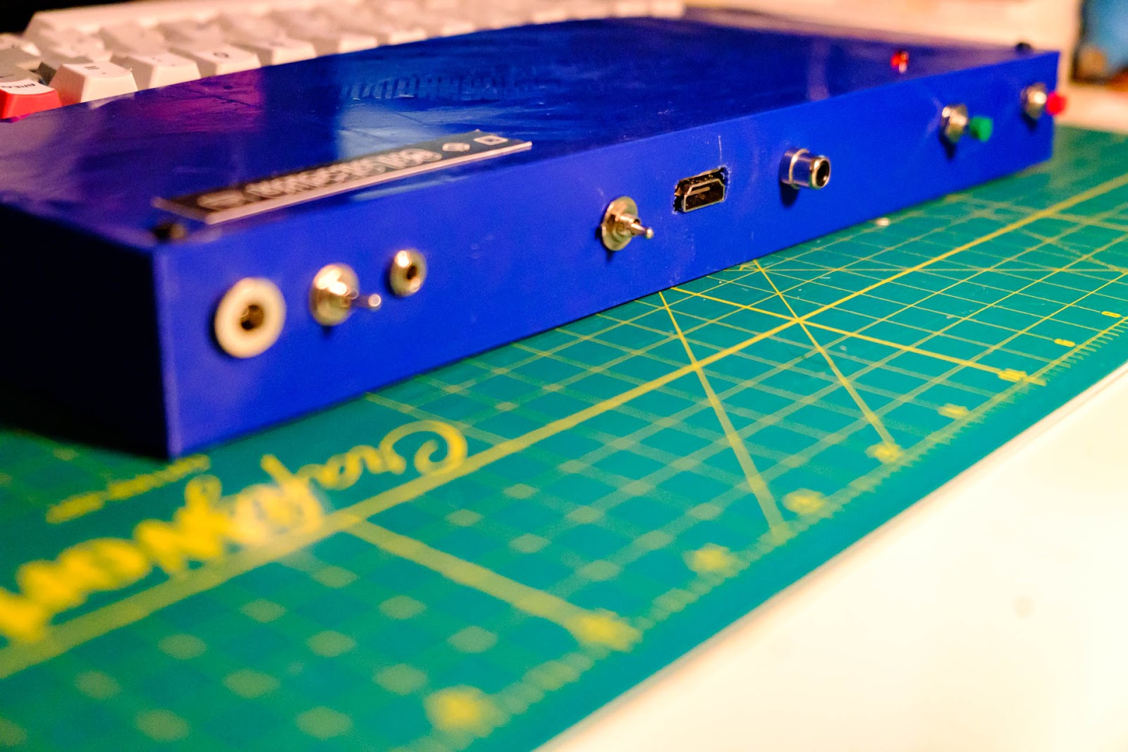
- HDMI: I integrated the RCA/HDMI adapter with the rest of the board
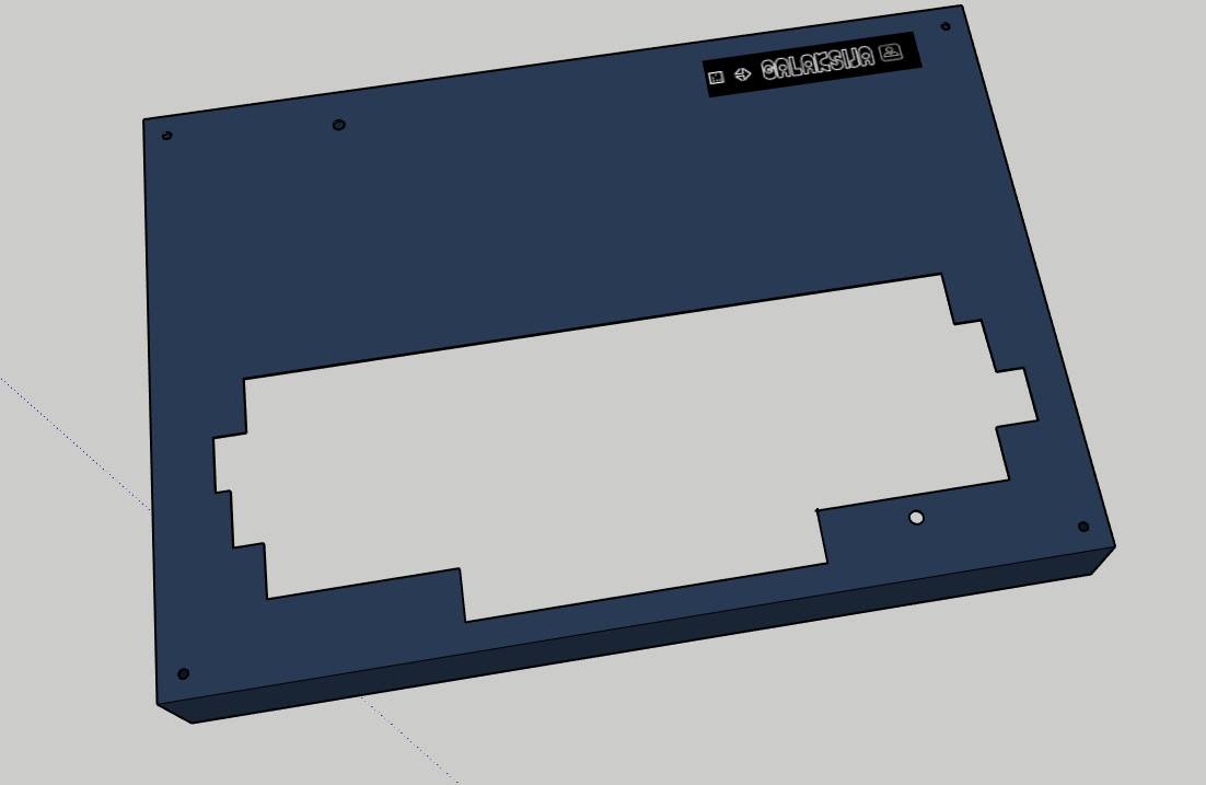
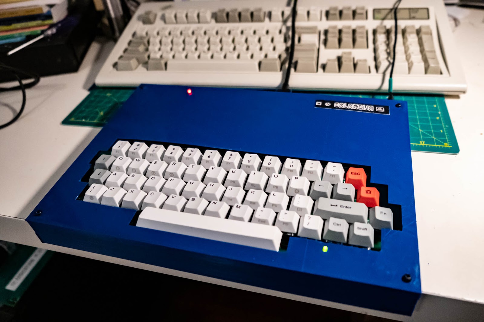
- 3D printed case: I designed a case in Sketchup and 3D printed it
- dump2gtp: I wrote a mini tool to backup Galaksija programs recorded in wav to the popular gtp virtual tape format. The tool is called dump2gtp since it uses MAME to dump audio files. I’m still working on it and the final version should convert wav to gtp directly.
Documentation for these mini projects and all the files are available on my GitHub.
HDMI
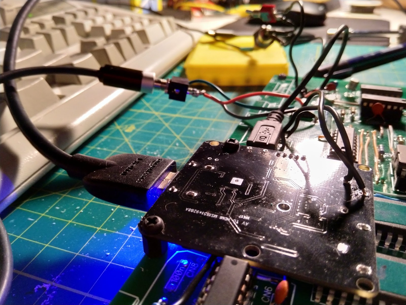
Since I don’t have an analog TV or monitor, I’m using a small RCA/HDMI adapter to connect my Galaksija to a modern LCD display. I noticed that the image is much better if the adapter is connected to the same power supply like the rest of the computer. I took out the adapter board from its case, drilled two holes in Galaksija’s board (with a lot of caution not to drill through any connections) and directly soldered analog video to it. Later on I also added a switch so I can use either analog RCA or HDMI video.
3D printed case
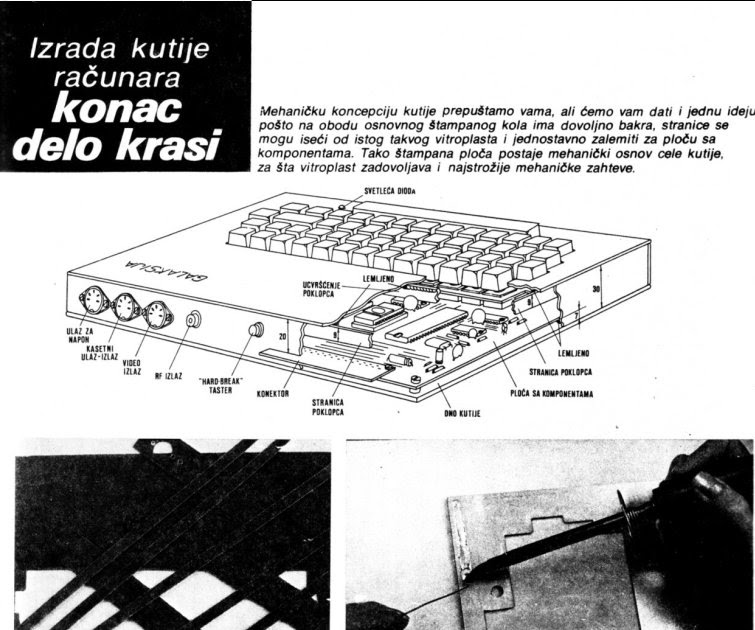
I wanted to make a case like the one from the DIY guide. The guide suggested using a blank PCB board as a cheap solution that can literally be soldered together. I even experimented with one of my spare PCBs, but I just wasn’t confident enough in my fiberglass cutting skills. Instead, I decided to go with a slightly more modern option that would still look very similar to the original. I made a 3D model in SketchUp and ordered a 3D print through craftcloud3d. For the bottom I used a plexiglass board. I combined the logos of MIPRO, Elektronika inženjering and Zavod za udžbenike i nastavna sredstva, the three companies involved in Galaksija production, and printed it on hard paper as a label. I’m pretty happy with the final product, and I’ve published the SketchUp file (with a few improvements based on my test print) on my GitHub.
dump2gtp tool
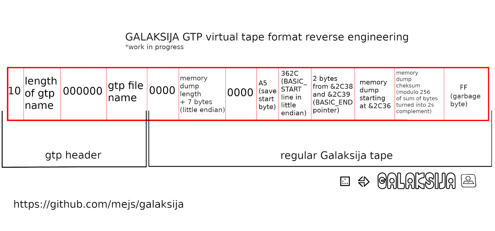
After I finally had Galaksija working, I wanted to be able to save the programs I write on the actual Galaksija as gtp files. Gtp is a popular format used by some Galaksija emulators, mainly MAME. It’s a simple file format that saves Galaksija files as hex bins instead of audio. Many programs available online are only available in gtp files and they need to be converted to wav to be used on real Galaksijas. Luckily, Tomaž Šolc wrote the gtp2wav tool which is available alongside his other great Galaksija development tools. However, I had no luck finding a tool that would do the opposite – convert a wav file to gtp. Such a tool would be very useful to archive old programs found on tapes, but also for saving new programs written on Galaksijas. Since I couldn’t find such a tool, I decided to make one. My tool uses MAME memory dumps and converts them to gtp. I’ve decided to use MAME as a stopgap since I still don’t know how to convert Galaksija’s audio signals into a hex dump directly. The process is:
- You save a program to a computer as wav
- You load it into MAME running in debug mode
- You make a memory dump from MAME into a txt file
- You use my dump2gtp tool to make a gtp file
- You verify the gtp file in MAME
This program is still in a very early development stage. Eventually I would like to make it a direct wav2gtp tool, without the need for MAME. It was fun for me to make since I learned a lot about the gtp format and how Galaksija saves programs on tape through reverse engineering the gtp format (since I couldn’t find any gtp documentation online). dump2gtp is available on my GitHub.
Bonus
Working on this project, I got very interested in small details, like the two different READY logos you can find on different Galaksijas. I’m pretty sure that Tomaž Šolc was the first to document this. Most character generator ROM copies you can find online only feature the Elektronika inženjering logo, so I made a few changes to the ROM file and made a version with the MIPRO logo too. Now you can easily choose which one to burn to your 2716 EPROM. Both versions are available on my GitHub.
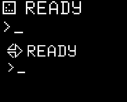
Bottom: Elektronika inženjering logo