Introduction
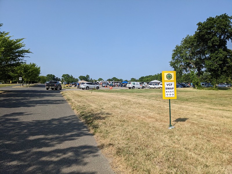
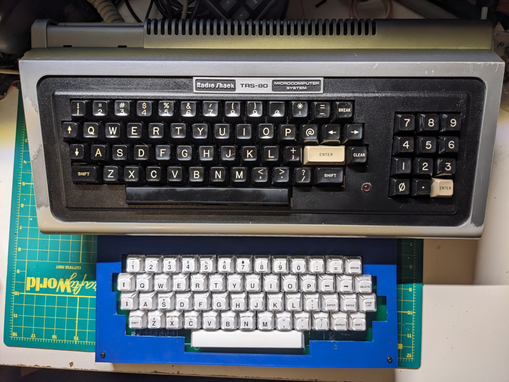
In early June I went to the VCF Swap Meet in Wall, NJ and picked up a supposedly functional TRS-80 Model I. I haven’t been very interested in TRS machines (other than owning a CoCo 2 for a moment) until I watched a video by Dejan Ristanović, one of the creators of the Galaksija project, who shared some less known facts about the history of the Galaksija and its connection to the TRS-80. In this video, Dejan mentioned how the TRS-80 influenced Voja Antonić, Galaksija’s designer. Voja’s first original computer design in 1981 was actually based on the TRS-80, but he significantly cut down the number of ICs, upgraded memory to 48K and implemented a number of other improvements. Voja did not have a name for this computer, but Dejan called it “TRK+ TRK-“. Additionally, TRS-80 Level I BASIC, based on the public domain Palo Alto Tiny BASIC by Li-Chen Wang, influenced Galaksija’s BASIC. As Dejan notes in his video, this influence was miscredited to Microsoft for decades due to the wrong assumption that Microsoft provided Level I BASIC for the TRS-80 (they did write Level II and Level III). Even the keyboard on the Galaksija is heavily influenced by the TRS-80, as you can see in the left and right side location of the arrow keys.
With all of this, I decided to get a TRS-80 Model I to better understand the prehistory of the Galaksija. I started looking for one online, but the few rare listings I came across went for hundreds of dollars, which was way more than I was ready to spend. Back in May, I found one at VCF East consignment for $100, but since I was exhibiting, I had very little time to purchase things and I missed out on it. I decided to wait for the VCF Swap Meet in June and figured there would be someone selling one.
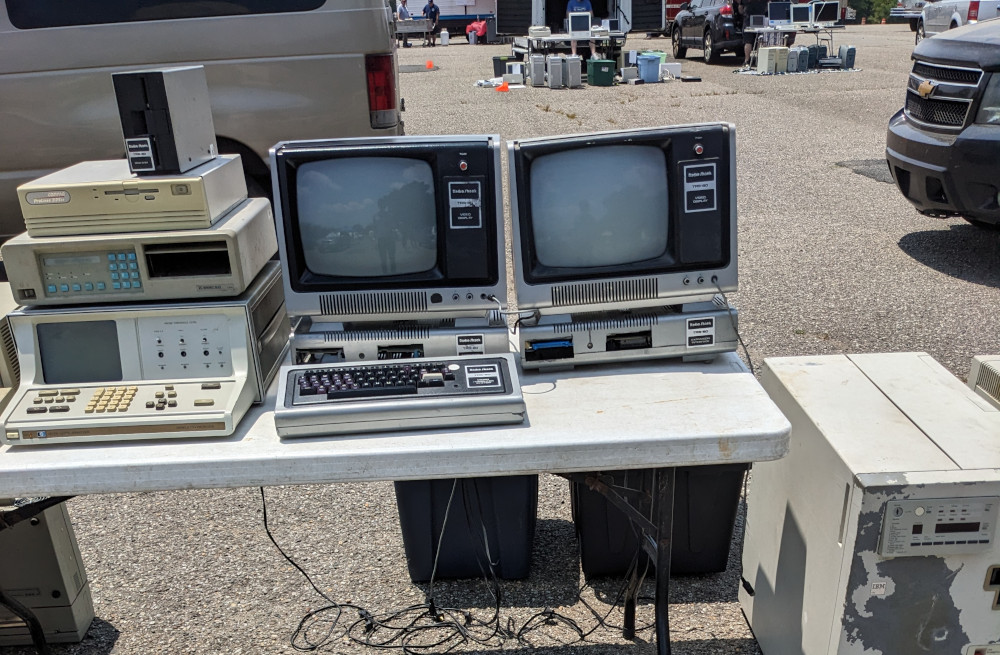
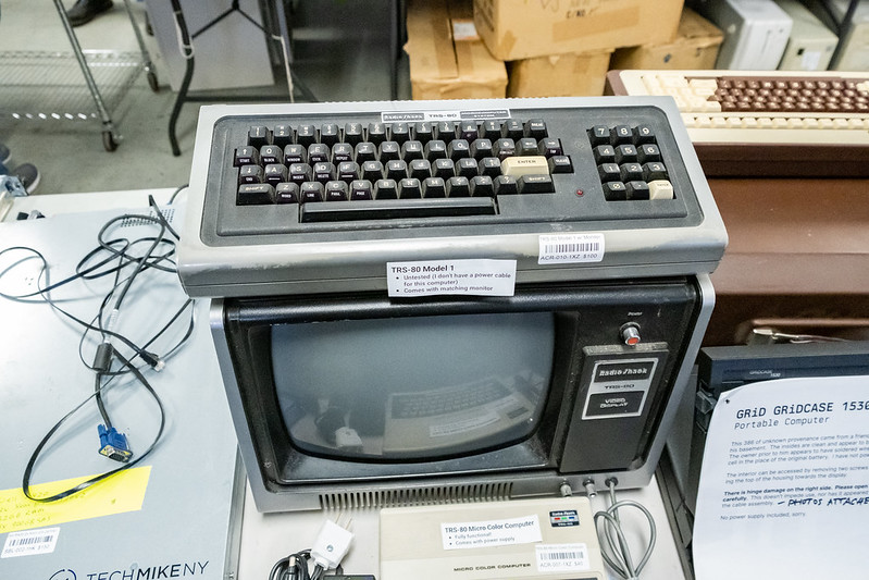
I was right! There was a vendor selling a couple of TRS-80 Model Is, with expansion interfaces and monitors. Since I took the train + folding bike to the swap meet, I had no way to transport the monitor (nor space at home to store it), so I made a deal to buy just the computer. The price of $95 was a bit higher than I was planning to spend, but the seller claimed it was fully functional, and the TRS-80 was the one thing I wanted to come home with.
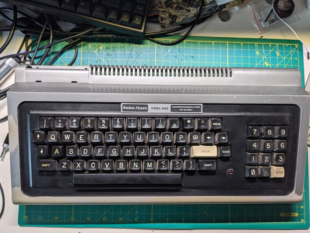
The TRS-80 was in “not great, not terrible” shape. Pretty dirty, with some paint scrubbed, but generally it was in decent enough physical condition. I started by making a composite cable for it (since I didn’t take the monitor). The TRS-80 Model I uses a DIN-5 connector with a 5V line that goes to the TRS-80 monitor, but otherwise it’s a regular composite connection. Once I built the video cable, I tried to turn the computer on. First there was a good sign — the indicator LED lit up! Unfortunately, I didn’t get video output. There was no output to my composite to HDMI adapter, so I grabbed the only CRT monitor I own — the Apple Monitor IIc. I got very faint output without horizontal sync. It was time to open the case.
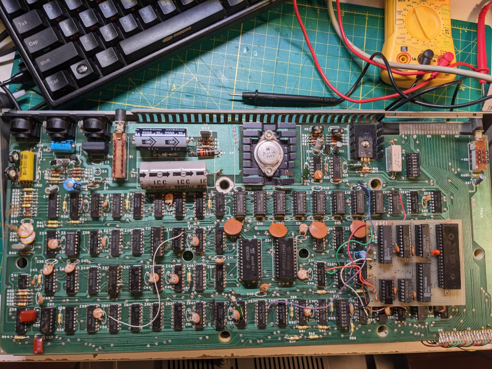
As soon as I opened the case I noticed 3 things
- there was a small daughter board with the Z80 CPU
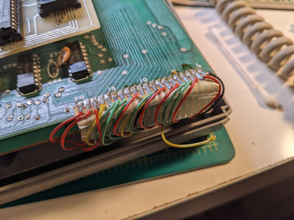
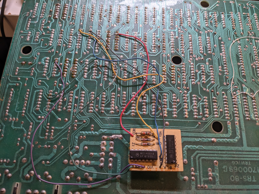
- the keyboard connector had disintegrated, and a previous owner soldered bodge wires on top of it
- there was significant corrosion on chip Z6 (74C04)
Video circuit repair
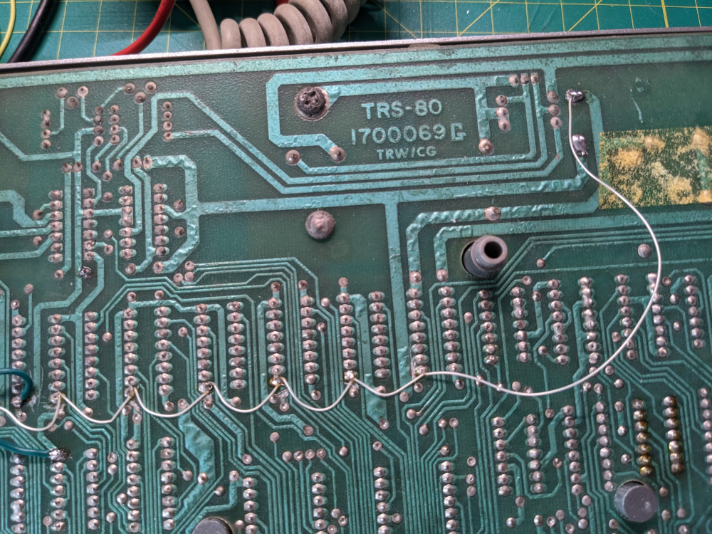
I started by dealing with the corroded chip. A quick search of common TRS-80 issues confirmed that Z6 is a part of the video circuit, and a very common component to cause issues. Getting the old chip out was difficult, and I had to cut the legs off of it to remove it. I also had to be very careful not to lift any pads, as the PCB is in rough shape. I put a socket in its place and added two bodge wires to fix the two connections that were broken by corrosion.
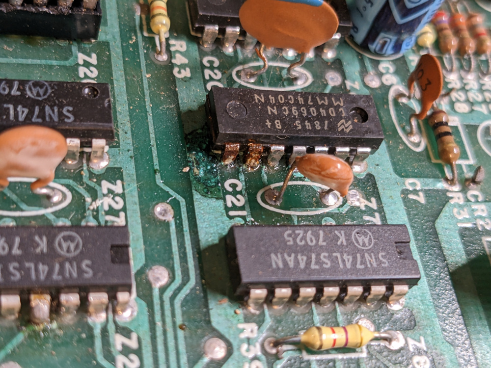

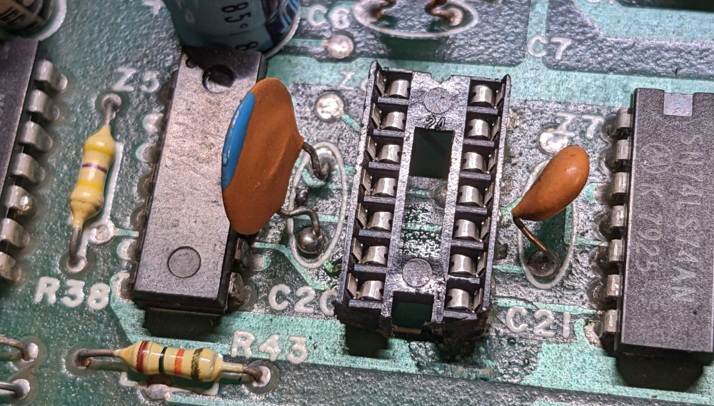
At this point I made a mistake that would take me a few days to figure out — I replaced the 74C04 chip with a 74LS04. Using an LS chip made sense to me since most of the other logic chips on this board were LS series. I later realized that I needed to put a CMOS chip there instead.
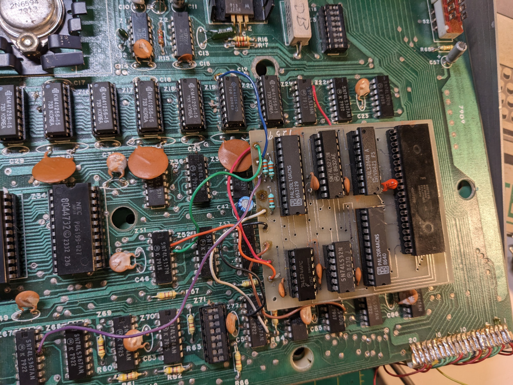
Anitek Supermem 256/512k memory upgrade
Even with this adjustment, I still had no video output. I decided to remove the strange daughter board. It had a bunch of wires soldered onto the board, including two going to 74LS157. At this point I noticed bodge wires going from the dynamic memory chips, connecting their PIN 9 (address line A7), to 74LS157 as well. Even though I didn’t yet know what this expansion actually was, I figured it had something to do with memory. I then noticed that the memory chips were 41256 — way bigger than the 4116s which would normally be the largest chips on this board to give it 16KB of RAM.
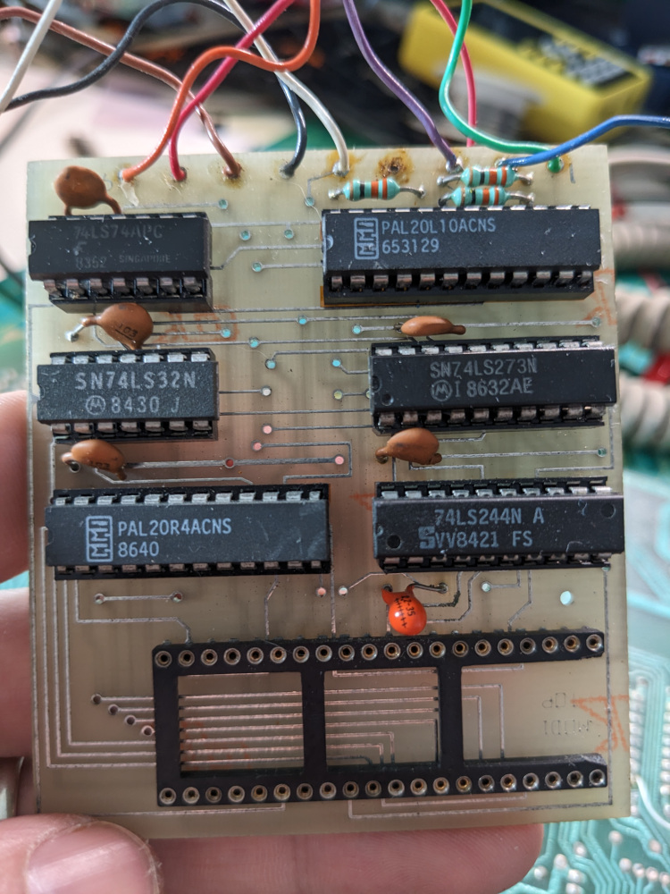
In the meantime, I tried to find out more about the daughter board expansion. I posted about it in the TRS-80 Model 1-4/4P Facebook group and soon found out that it was the Anitek Supermem 256/512k memory upgrade from the late 80s. The board with the PALs is a bank switchers and logic chips to handle the 256 cycle refresh memory chips.There’s more info in this VCF forum thread. I decided to take it out for now and perhaps try to get it working later.
Video circuit repair continued
I fully removed the daughter board, and moved the Z80 back onto the board. I tried video output again, with no luck. At this point I started looking around the dynamic memory chips again, and I noticed a number of modifications — cut traces, bodge wires. I pulled up the datasheets for 4116 and 41256 RAM which confirmed what I expected — there are a few differences between them, primarily in terms of power requirements. 4116 needs -5V and 12V in addition to 5V. 41256 only needs 5V. The modifications gave 5V on pin 8, which is 12V on 4116. -5V was completely removed (originally pin 1), while the pin 9 (originally 5V on 4116) was connected to 74LS157, presumably to be able to use address line A7.
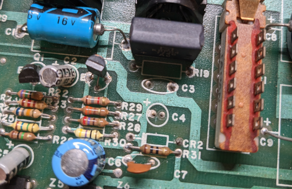
I also noticed that a number of passive components were missing from the board, including R19, C3, C4 and CR2, which according to the schematic are a part of the -5V circuit.
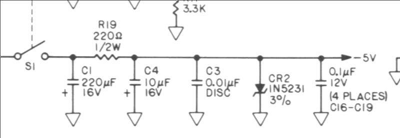
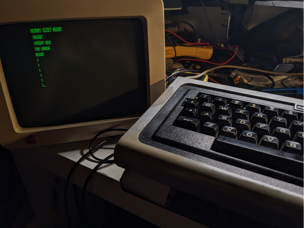
Even though the 41256 RAM wasn’t using the -5V power, I figured it wouldn’t hurt to put those components back. I did not have an IN5231 compatible diode, but I did put C1, C4, C3 and R19 in place. Once I did that, I finally got something on the screen!
I got a pretty picturesque error – the computer was looping with MEMORY SIZE ?SN ERROR. This had me stumped for a few minutes, because I thought it was a memory error. However, this article helped me understand that the error was simply due to the keyboard being disconnected.
Keyboard connector repair
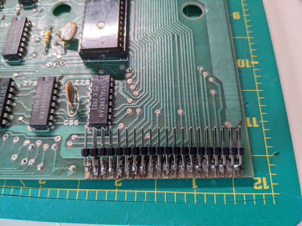
I had planned to tackle the keyboard later. The bodge wires the previous owner put in place were falling apart, so I decided to completely replace this with a ribbon cable. I got the idea from the aforementioned article. I’ve made some ribbon cables before, so this was a relatively simple job. I soldered angled pins aimed inward. This is important because otherwise the ribbon cable wouldn’t have fit in the case
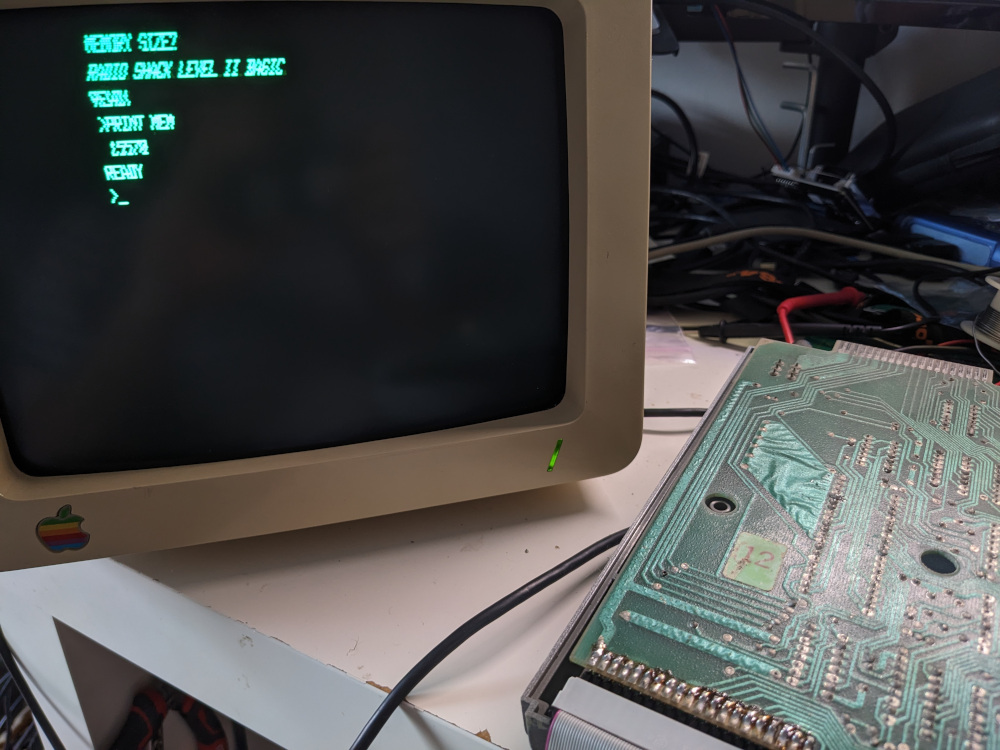
Once I put the ribbon cable together, the computer finally booted successfully!
Memory restoration
I was able to issue a few commands, but very unreliably. I kept getting errors like ?OM ERROR. PRINT MEM showed only 81 KB available. 41256 RAM was working, but with an extremely limited amount of memory. I went back to the data sheets for the 4116 and 41256, trying to get the 41256 to basically behave as the 4116. Once I tied A7, which had been going to pin 4 of 74LS157 and the daughterboard, to ground, I finally had access to all 16K of usable RAM (max for the TRS-80 Model I without expansions).
XRX modification and cassette input
The computer was functional, but the screen output was quite wobbly. The next step was testing cassette input. I made another cable, this time making a 3.5mm to DIN-5 cable. I got the TRS-80 tool to convert .cas files to wav and converted a few programs. Before attempting tape load, I made sure that the XRX modification was on the board. This modification is a small PCB with two logic chips on the bottom of the board, meant to improve loading from tape. Initially I took it out because I didn’t know if it interfered with anything. It probably made no difference as it was an official fix/upgrade that Radio Shack would add to existing computers due to a bug in Level II BASIC that introduced loading issues. Mine is likely version XRX-III of the XRX. XRX was made redundant by version 1.3 of the Level II ROM.
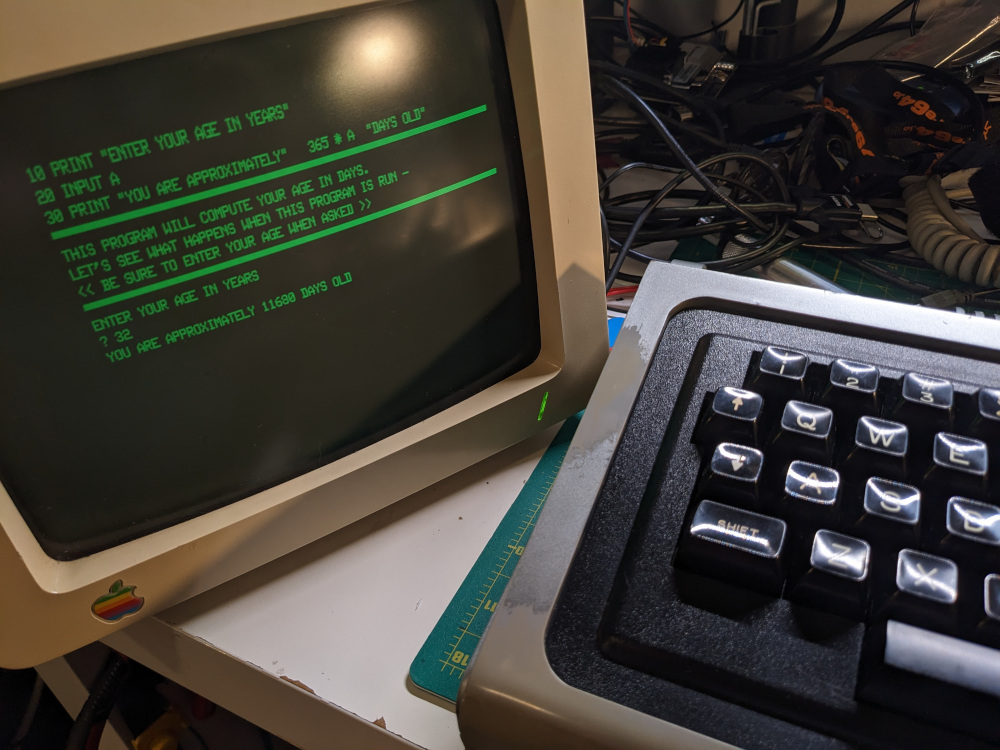
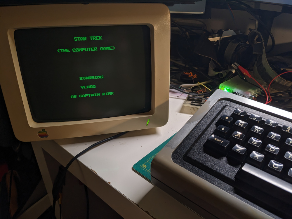
Once the XRX modification was back on the board, I successfully loaded Star Trek!
Keyboard cleaning and repair
I still had to deal with the image wobble, but I took a break to wash the keys. I also had to repair a few keys that weren’t responding well. Adding some fresh solder the key switch connections seemed to fix the issues reliably.
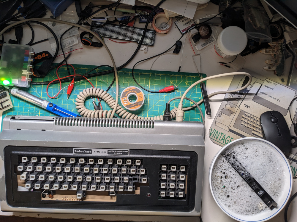
Image wobble repair
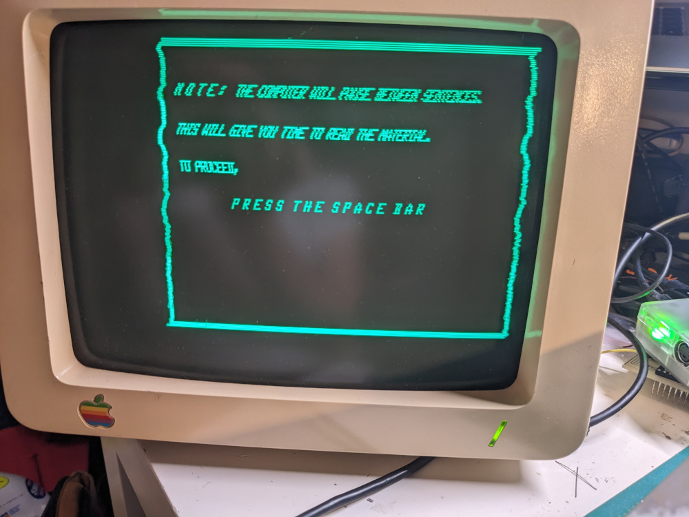
The last thing to fix was the image wobble. It was very visible when looking at some kind of graphic like the frame below. Following suggestions online, I started replacing some passive components like electrolytic caps and resistors that are a part of the video circuit.
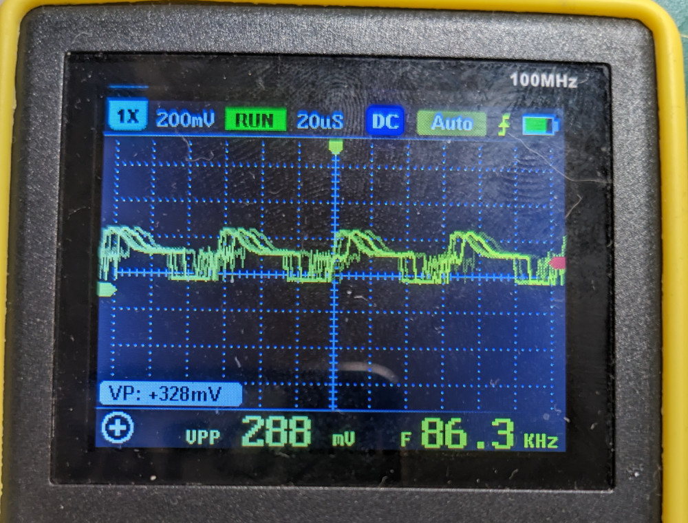
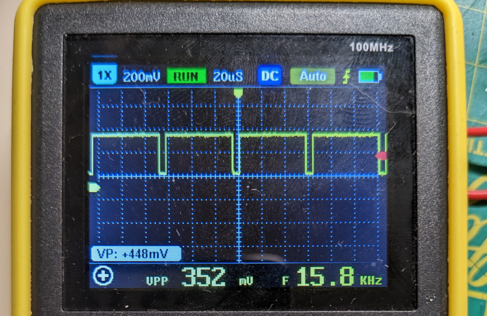
I had no luck, not even when I replaced the 4 variable resistors in the video circuit (R20, R21 and R5, R6). I then noticed the difference in the video signal HSYNC when comparing its wobbly signal to the good one from an Apple //e:
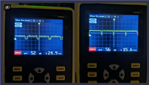
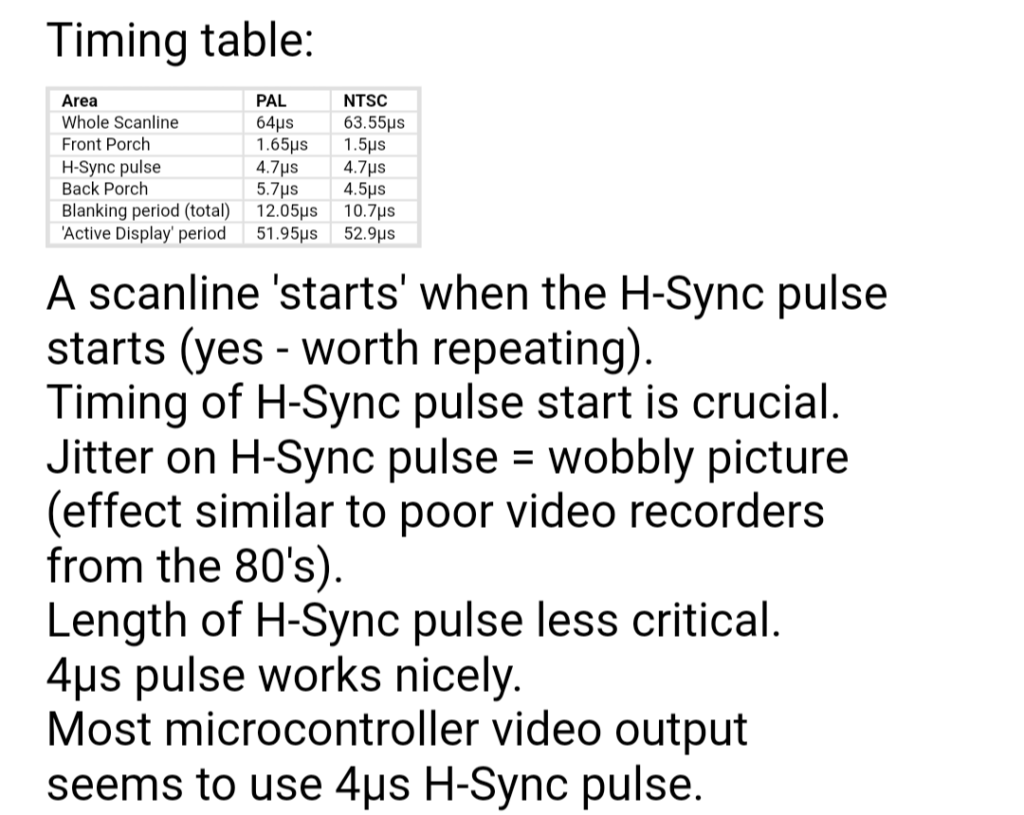
It looked like my H sync pulse was closer to 20μs vs 4μs cited in this article, but it was “jitter on H sync pulse = wobbly picture” that caught my attention because I definitely had jitter on that signal.
TRS-80 power supply issue
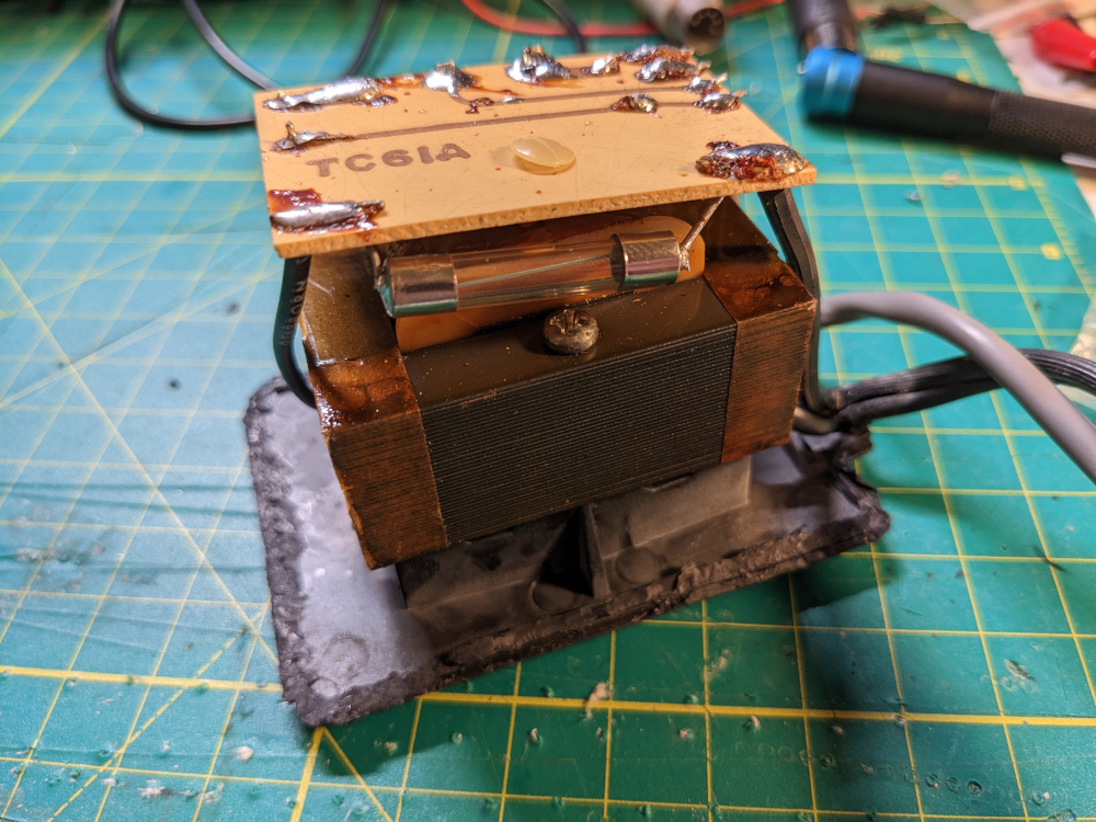
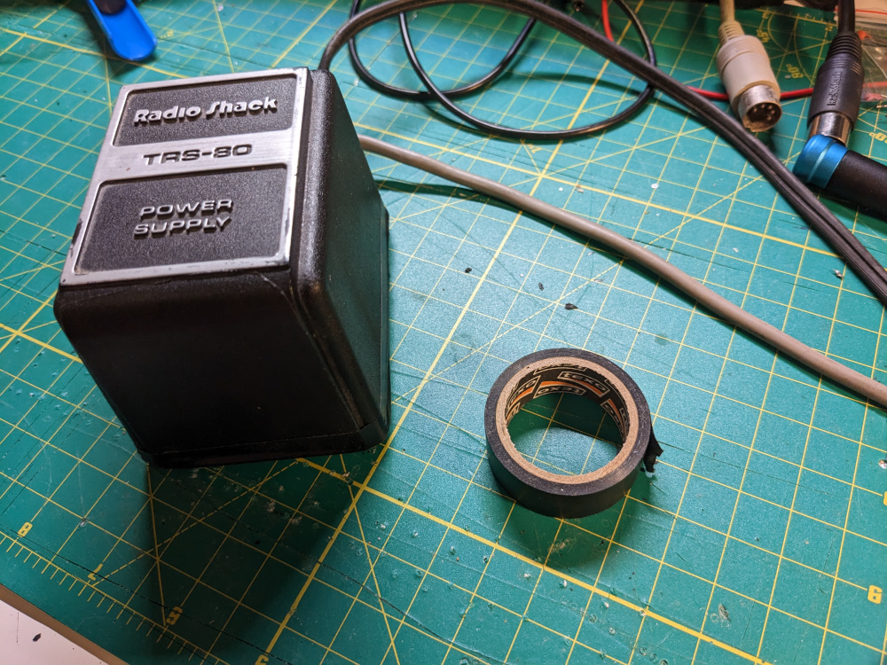
I had also tested the power supply and noticed some issues — I got 17.2V DC and 19.2V AC. Per the TRS-80 Microcomputer Technical Reference Guide AC should be 14VAC and DC should be 19.8 VDC. I even opened the power supply and tried changing the single diode. This had no effect and I accidentally blew the 40 year old fuse so I had to replace it with a new one. Opening the case was extremely difficult and it required me to cut the plastic. When I put it back together I used electrical tape to close it back up.
Wobbly video repaired
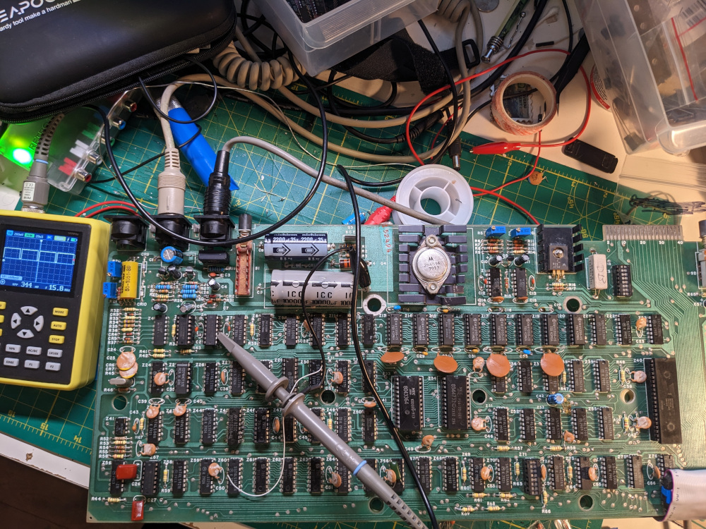
After replacing at least a dozen passive components around the video circuit, I finally took out my scope and started looking at the signal, starting from the composite video connector, until I found the source of the noise which I presumed was the cause of the wobble. I ended up finding something wrong on pin 10 on Z6 74LS04.
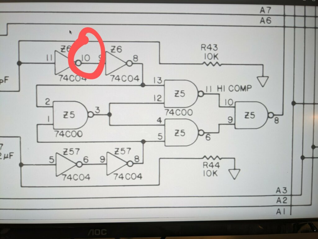
At this point I remembered that I replaced 74C04 with 74LS04. As soon as I put a CMOS version in its place (74HC04), the wobble went away for the most part.
Conclusion
The image is still not 100% fixed (for example, I still can’t reliably use the composite to HDMI adapter) but it is fully usable with the Apple Monitor IIc. I will likely need to obtain/build a new power supply to know whether that’s what’s been causing any of my issues. This post may expand in the future, but for now it covers most information about my repair of this TRS-80 Model I. As most of my repairs and restorations, this post is based on a thread on Mastodon.