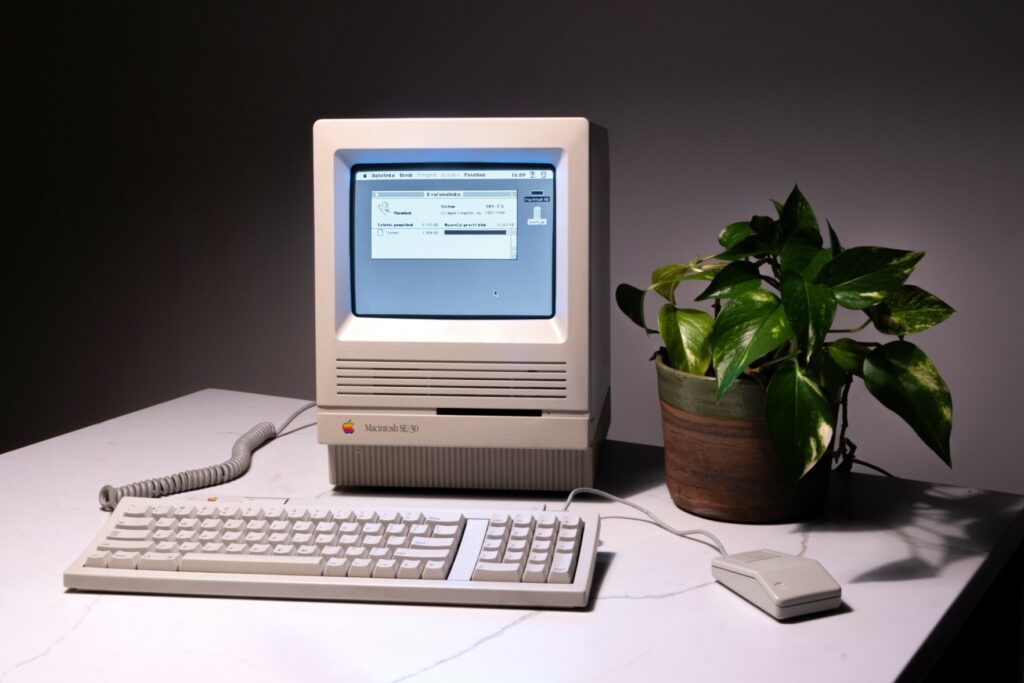
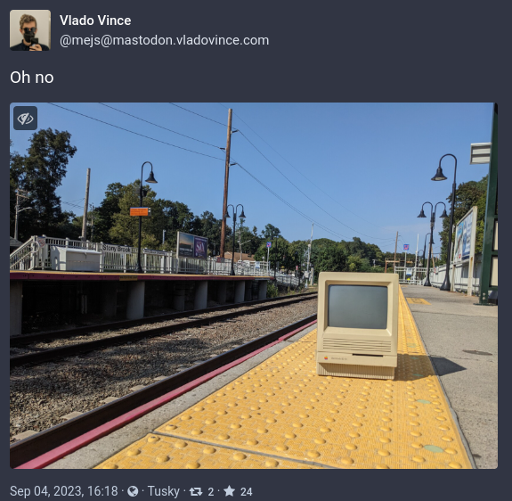
In early September I published a post on Mastodon, with what was meant to be a humorous comment. “Oh no”, I said, implying that there is something wrong with getting a highly coveted Macintosh SE/30. The joke was accompanied by a photo of a small beige Mac on a Long Island Rail Road platform. If only I knew how many times I would repeat that “oh no” over the following few months.
At the time, the “oh no” mostly referred to my concerns about bringing yet another largish vintage computer into a small Brooklyn apartment. We had recently moved, and I hadn’t even unpacked all my existing old crap. Plus, this would be my third compact Macintosh, joining a regular SE and a 512K I restored recently (with quite a lot of trouble). In fact, I was so concerned about space and so sure that this restoration was going to be quick and painless, that I immediately posted about looking to find a new home for the SE. Oh how quickly I would learn that storage would be the least of my issues with the SE/30.
The two boards
Considering the context, it’s not surprising that this was an impulse purchase. It was the Labor Day weekend, and around noon on a Monday I came across a post in one of the vintage Macintosh Facebook groups where someone posted a photo of a wall of compact Macs, looking for buyers to take them all. I immediately noticed a single recognizable SE/30 among a few SEs and Pluses. And then I noticed the location — just a train ride away from me. While the seller offered to ship items as well, I knew that heading over asap was the only way to ensure I would get it, dangers of shipping compact Macs notwithstanding. I quickly got in touch and confirmed with the seller that I would be there in a few hours. A relatively quick train ride later, I showed up and got to inspect the Macintosh I would be taking. It was immediately obvious that there had been battery leakage in the case – the seller allowed me to open it up and we confirmed that the board was badly damaged. While I hesitated, they offered to include another SE/30 board, in great physical shape and recapped as well, for the price of $100 total. I had already spent a bit of time and money to get there, so I gladly agreed and took the SE/30, and the extra board, back to Brooklyn.
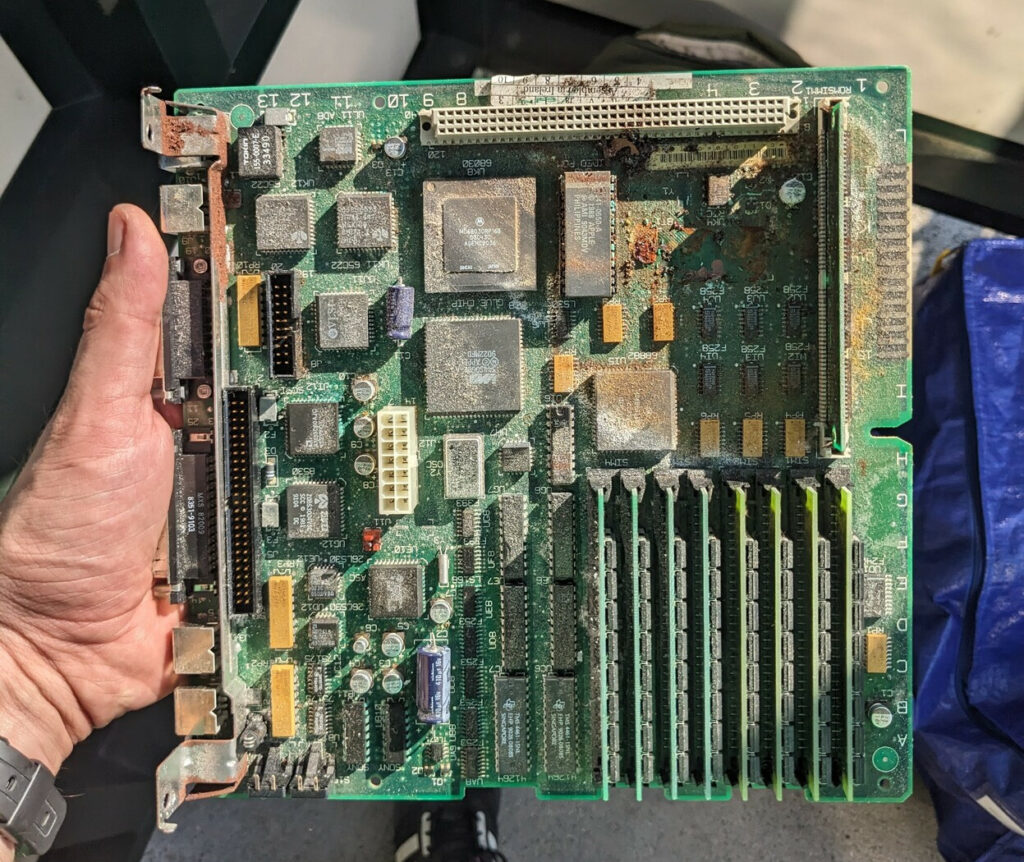
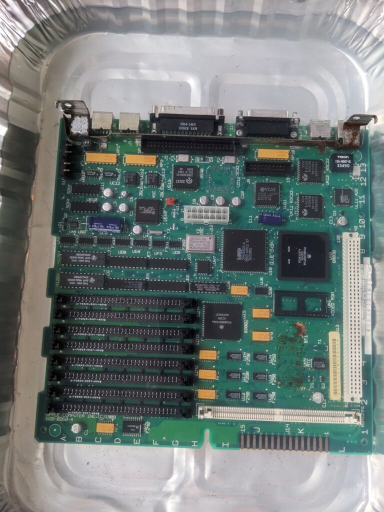
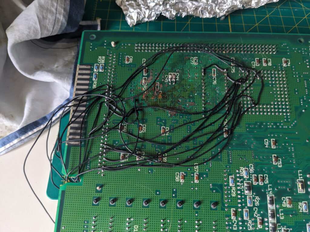
Board #1 — the battery bombed disaster

The board that was inside the case was disgusting. The photos included here were taken when I got home, but by that point some of the most visible dirt and dust was gone (see above how it looked like originally). It was clear to me, even with my limited experience with battery damage, that there should be no attempts to turn this board on without serious cleanup efforts. The battery holder fell off the board, some bottom caps were gone too, and the battery (and capacitors too) have started to do damage to a lot of components.
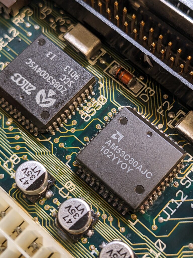
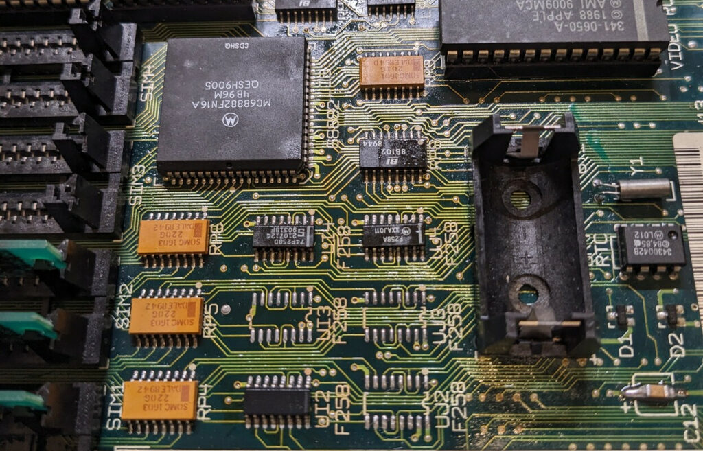
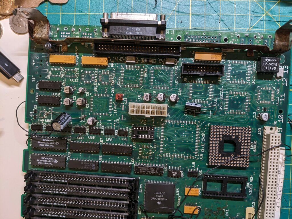
Board #2 — the misleadingly good looking catastrophe
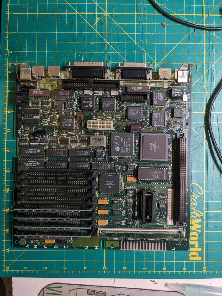
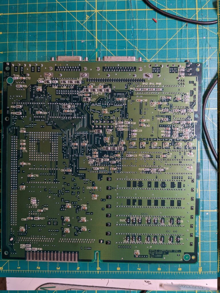
In comparison, the second board the seller gave me looked great! It was clean, with no visible damage. Even the capacitors were replaced, and whomever did it did a very clean job. I thought I had hit the jackpot — as long as the analog board in the case was fine, this would be smooth sailing.
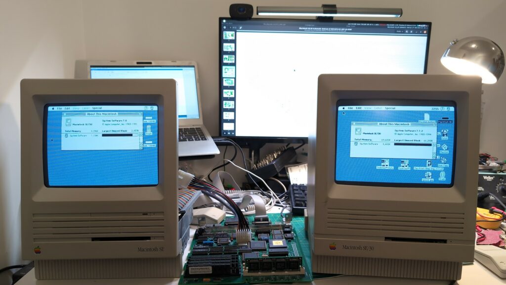
The smoke test
Before venturing to test board #2 (I wouldn’t even consider plugging board #1 before a lot of cleanup), I went ahead and checked the analog board, PSU and the monitor. Plugging my known-good SE board, it booted right up. Good sign!
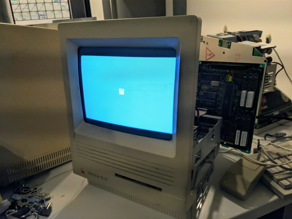
This optimism continued for a while longer, as I connected board #2 and got the floppy disk icon! Things were looking up, until I tried to boot from a BlueSCSI which didn’t even get detected. While that was a bit discouraging, I pulled out my FloppyEMU and tried to boot into a system. The system would start loading, but then fail with a flashing screen:
This happened with any system I tried. So there may be some work left to do, I thought. I couldn’t predict just how much work.
The early days of repair
I’ve been repairing electronics for as long as I can remember, but I really got serious about vintage stuff about 3-4 years ago (remember the still ongoing pandemic?). During this time, I’ve built a couple of 8 bit computers and restored quite a few more. I even designed a few hardware projects from scratch. And this was my third compact Mac — I expected a few days or two weeks of work max to get this resolved. I started with the easy stuff. Everyone says you should recap your Macs, so even though this board was clearly recapped, I went for it anyway. This did absolutely nothing, the SCSI still wouldn’t work and booting into any system failed immediately.
Checking connections on the SCSI chip wasn’t helpful — the 53C80 chip had good connections to everything. Since the chip was still available on Mouser, I got a new one and replaced my old chip. This was the beginning of my long and arduous road of teaching myself how to properly solder and desolder surface mount components. Yes, everyone says get yourself something worthless like a DVD player and practice, but I was:
a.) Impatient
b.) Convinced that I already knew how to do it based on limited previous experience
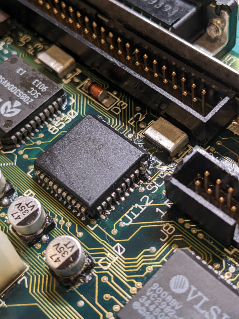
Looking back, I absolutely had no idea what I was doing (as will become apparent later on). I was aware of the danger of damaging the board when removing components (I did have some experience), so my first attempt at removing the SCSI chip included the use of chipquik, a low melt solder that stays liquid long enough to remove a component. I combined this technique with the use of a heat gun (yikes) and I managed to lift a pad. I did make a small bodge connection to the trace it connected to, but this was a good indicator of issues to come.
The good news was — SCSI actually came to life! The computer would attempt to boot from it, but sadly it would again fail to load a system, crashing with a variation of flashing welcome screens. At this point I came across a video that gave me hope for a moment.
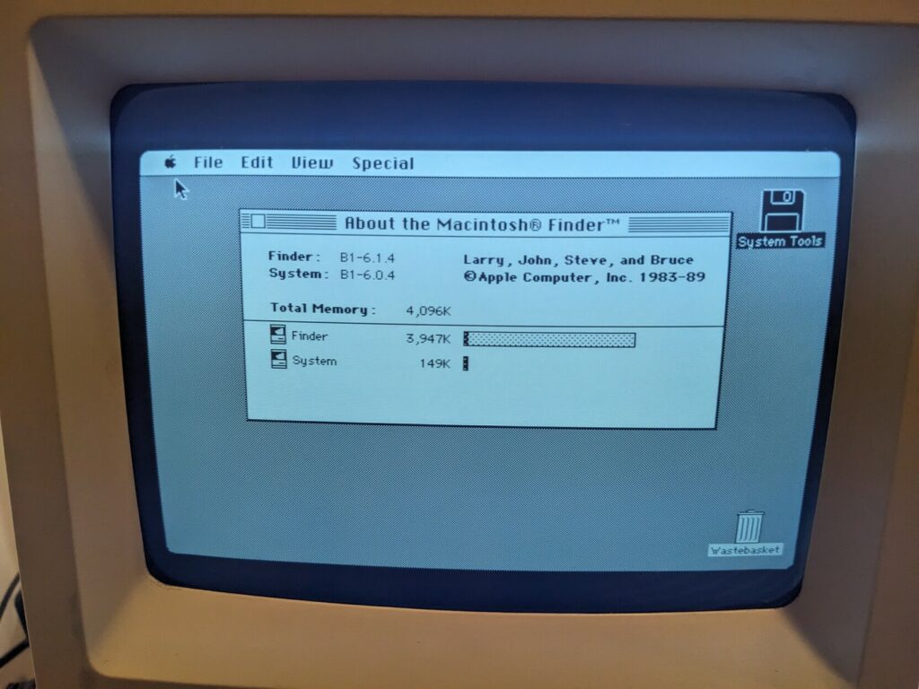
In this video, Joe comes across an issue that looks the same way as what I was experiencing. Flashing screen that wouldn’t complete system loading. He then manages to boot into System 6.0.4 and concludes that the issue is related to the FPU. He bodges the 5V rail to the CS line on the FPU, effectively disabling it. Afterwards he’s able to boot into other systems as well. This got me excited, and lo and behold I managed to boot into 6.0.4 as well!
The excitement was short lived. The system immediately crashed, and subsequent attempts to boot it failed as well. I tried the CS trick to disable the FPU without success. This seemed like a red herring. But it did convince me that there was some connection to the FPU. I placed an order for a replacement. I also ordered a Rominator II on the off chance that the issue I had was related to the ROM. While I was at it, I also ordered replacement F258 and F253 muxes. By this point I learned about their role in the memory bus and I convinced myself that the issue must lay somewhere among them. While waiting for all these parts to arrive, I tried every possible memory SIMM combination, with no success. I used confirmed good SIMMs, in combinations of 4, failing each time in the same way. The problem was somewhere else.
The first to arrive was the Rominator. It immediately failed in the same way. Then I tried the F258 and the F253 muxes. Same issue. I then replaced the FPU. Same issue.
Wait. No. Not just the same issue.
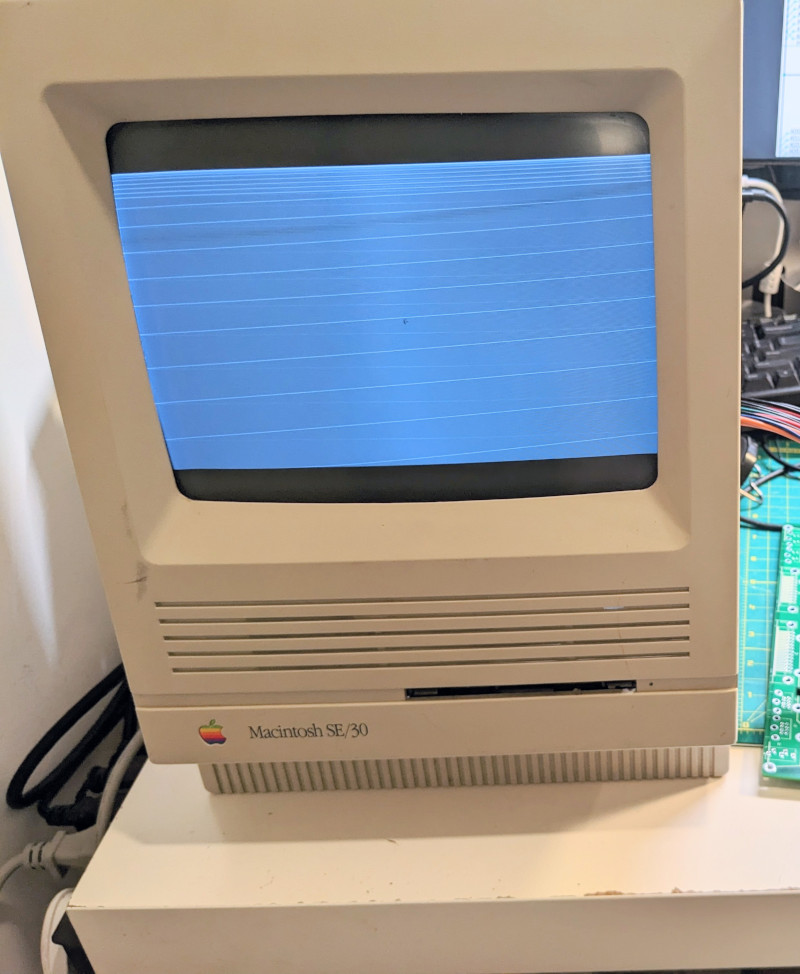
Collapsing image
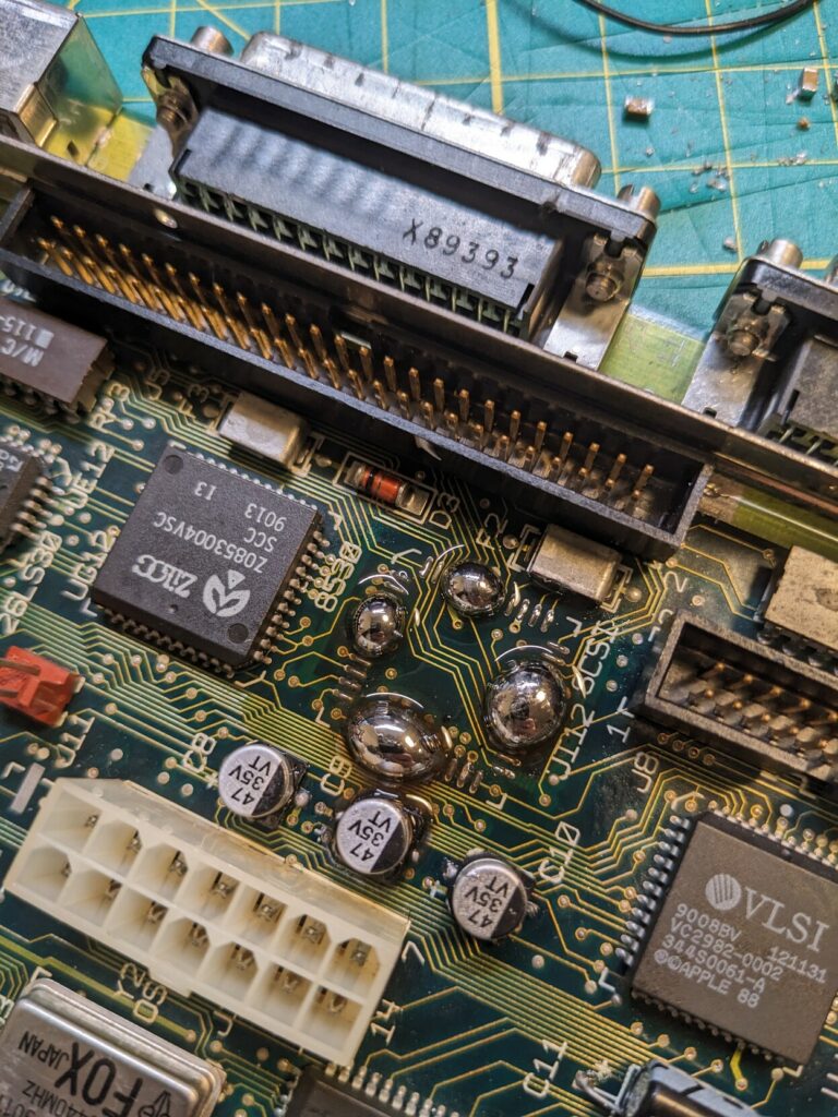
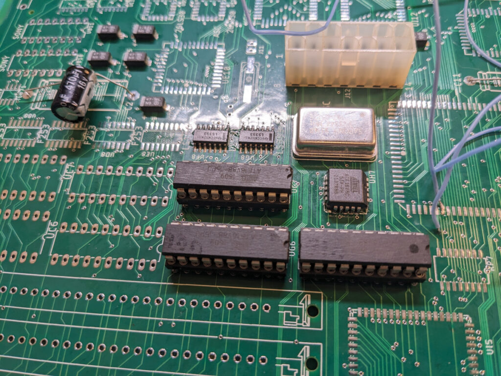
A few minutes after soldering on the new FPU, the real issues began. I started to experience what I’ve been calling the “collapsing image” problem. At this point, I began to panic. Instead of taking it slow and thinking this through, I started to make assumptions and switching out components from the other board (somewhat cleaned up by now). Is it the PALs? I started to program new GALs. Is it the CPU? I even replaced the 68030, a very difficult task considering its 132 pins.
At this point I’m making mistake after mistake by reacting without a plan or process. Looking at the schematic, I very early on hone onto the UH7 chip which takes the 32Mhz clock. I observe that clock line collapsing, and see the effects on the screen. Early on the computer chimes, first a good chime, then the bad. Soon, the chime completely stops. Sometimes the jail bar (one version of simasimac) shows, sometimes for a few minutes until it collapses without fail. The bus is dead.
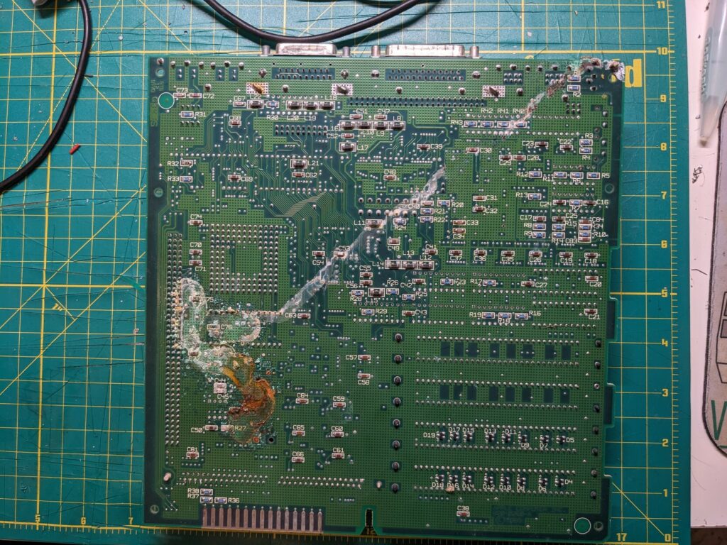
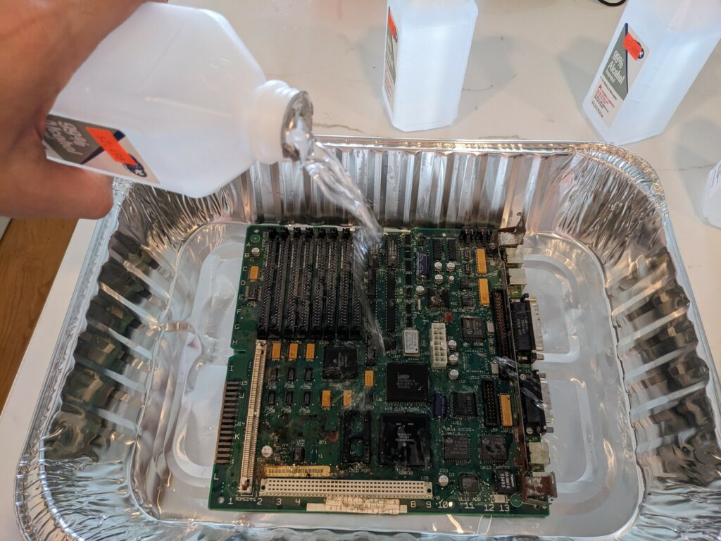
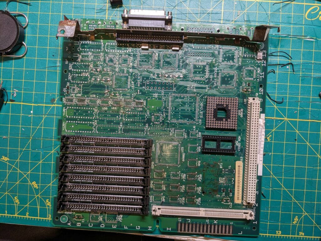
Cleaning up board #1
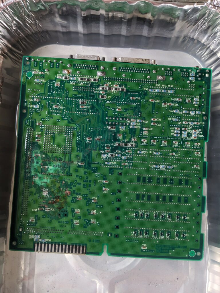
At this point I’m going to do a short detour. Before completely blowing up my repair with the collapsing image problem, I worked on the battery bombed board (board #1), cleaning it up and eventually trying to re-connect broken lines. While this effort was ultimately completely unsuccessful, it was useful as it cleaned up many components that I would later on successfully reuse. I started by submerging the board in vinegar and leaving it overnight. I then scrubbed it with a toothbrush. Finally, I bathed it in IPA and washed with distilled water.
The results were not horrible:
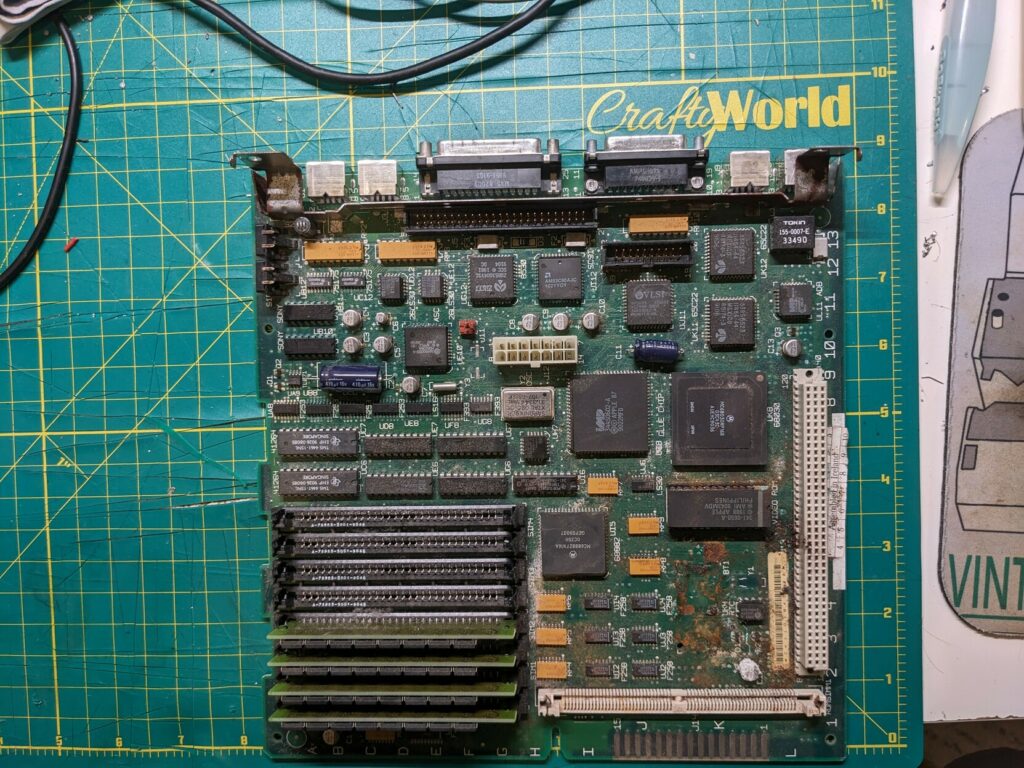
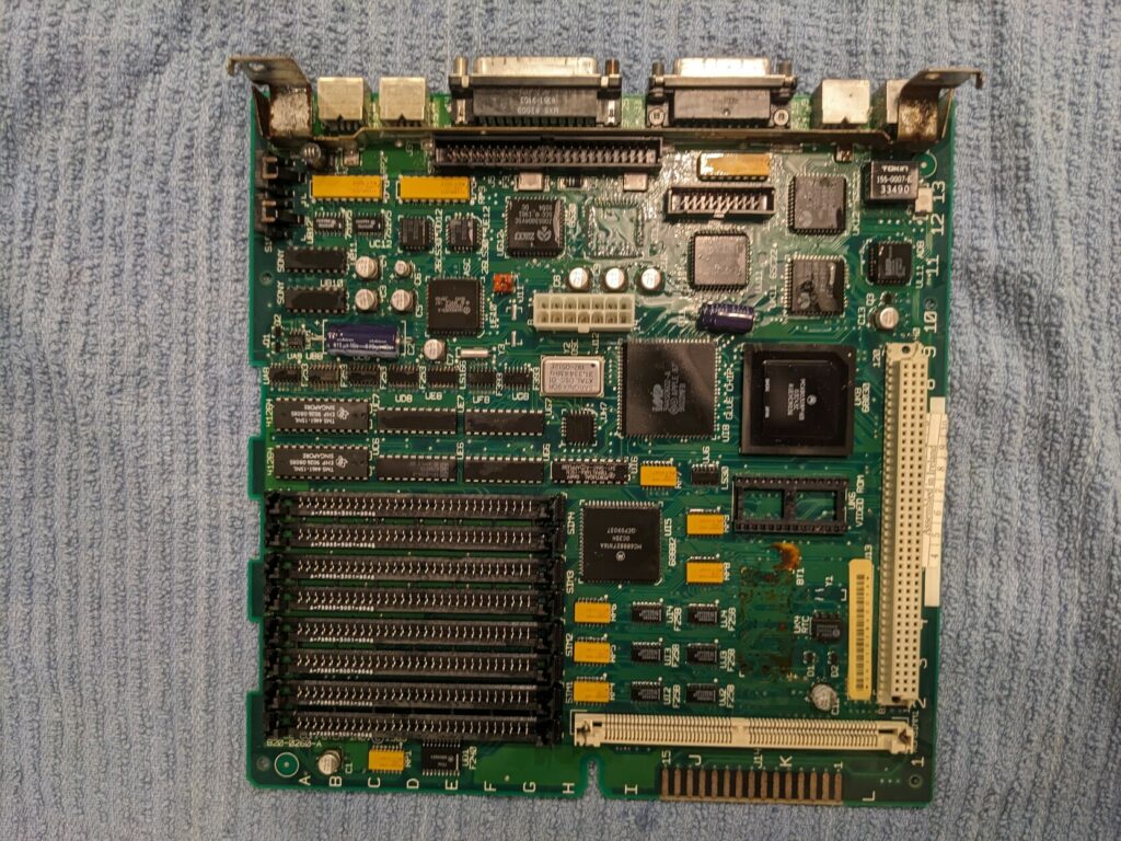

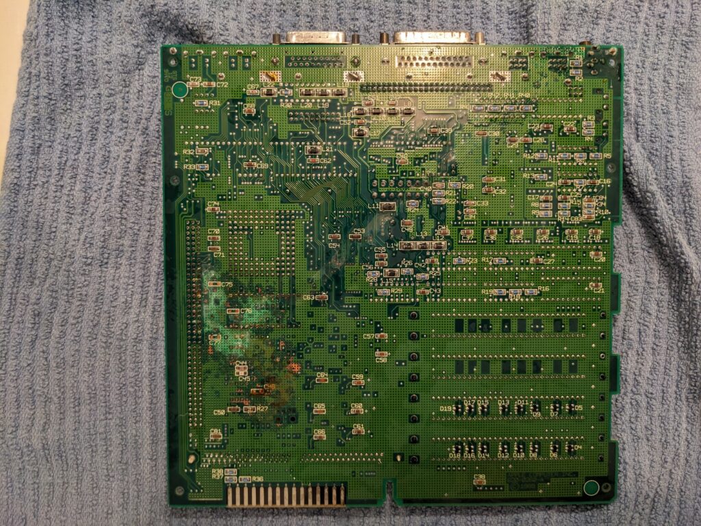
In retrospect, I was able to save most components. The exception were the SCSI chip, the FPU, the ROM SIMM and some of the video logic PALs that I damaged while desoldering them.
At this point I also tried to recover this board by reconnecting broken traces and replacing disintegrated resistors and capacitors on the bottom. This never progressed past the simasimac (jail bar) pattern.
Once I encountered the collapsing image issue on board #2, I first used board #1 as the donor for UH7 chip. I flipped the chips between the two boards, and suddenly, board #2 which wouldn’t boot but at least had the stable jail bar pattern now started exhibiting the same collapsing image symptom!
Moratorium and decision to rebuild
After the initial collapsing image problems started and I had no success resolving them, I had to take a break. I gave myself a 2 week moratorium during which I wouldn’t touch either board. Instead, I started looking into alternatives. I was sure that between the two boards I had enough good parts for at least one working SE/30. Additionally, with all the removal of components from board #2 I was getting worried that I am just damaging it further. By this point (early October) I had lifted a few pads and without proper tools (I was still using a heat gun!) I was likely damaging traces inside the PCB as well (the SE/30 uses a 6 layer board!). I arranged to get an SE/30 reloaded board, designed by Bolle from 68kmla.org forums. I arranged a single board from a fellow enthusiast, and they threw in some hard to find components like the RAM and ROM sockets and the PDS slot. I placed a large Mouser order for as many other replacement components to minimize the amount of items I would need to remove from old boards.
Parts harvesting
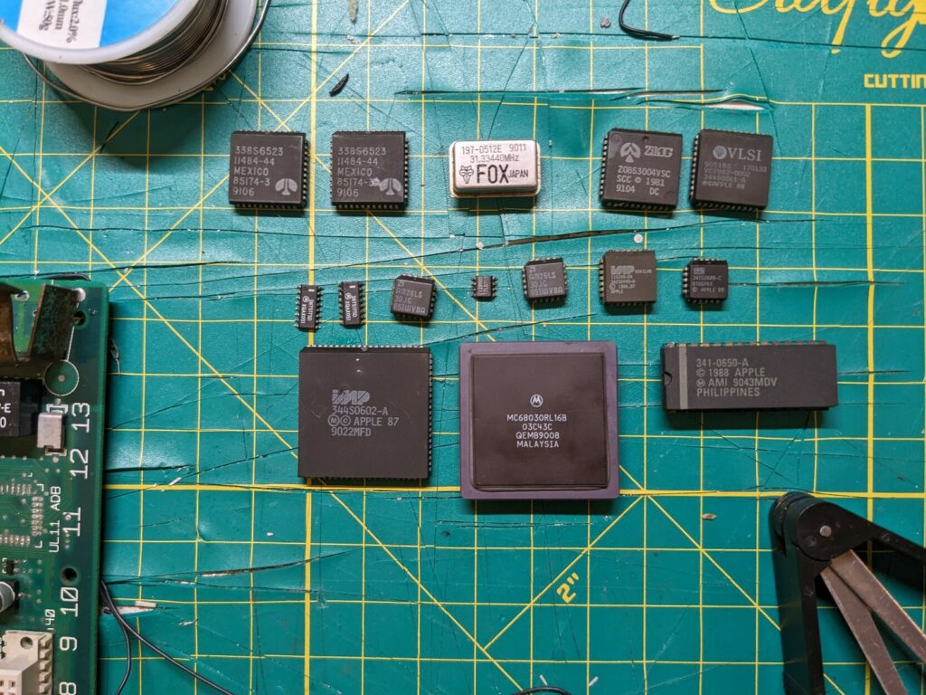
I decided to get my parts from board #1 (battery bombed one). I still had some hope for board #2, and I felt that destroying board #1 in the process of component removal would be acceptable. The difficulty of removing the parts varied. I finally went ahead and got a hot air station (something I should have done before ever touching an SE/30) and with enough heat any soldered component will eventually come off. The biggest problems are sockets with plastic parts. Luckily for this first new board I had no need for plastic components. The most difficult piece was the metal “frame” which clips into the chassis. By the end the board was full of scratches.
Board #3 – Reloaded attempt 1
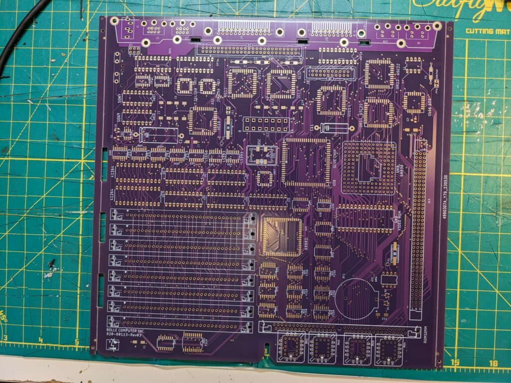
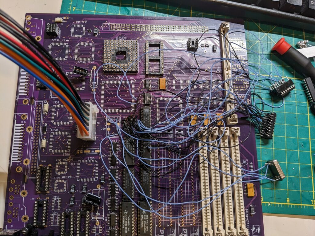
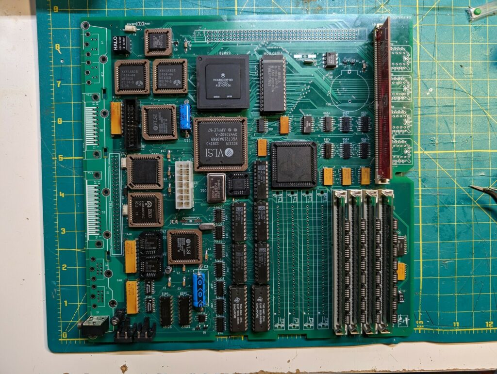
I got my reloaded board in mid October. It came with the bottom pre-populated, sans the ferrite beads which I sourced from the donor board. I was excited and determined to get it right. I had all the parts ready. I had fresh soldering tips and a jar of flux (remember this foreshadowing for later). I set up music and embarked on populating the board. I took ample photos documenting the process, and I completed the build in some 8 hours. I flipped the switch.
Not only did the board not boot, I had an actual visibly detectable short somewhere. It didn’t even pass the smoke test.
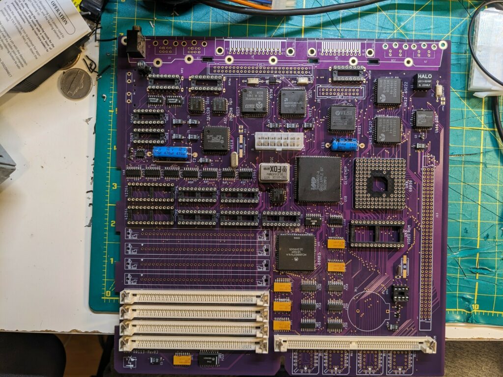
Months later someone pointed out that in the image above I actually have an incorrectly soldered IC. Look at the ADB chip. It should be rotated by 90 degrees left. I soldered it like that because I was using board #2 to look at chip orientation, and that particular ADB chip on that board has the part number rotated.
I immediately lost steam. I spent days tracing the short, and frankly I don’t think I ever actually found it. But I did get the board to a state where it did the exact same thing as the other two boards — the image was collapsing after a few minutes.
Rebuilding the clock and video sync circuit
At this point I gave up the dream that this was going to be quickly resolved. I tried the analytical approach to just get a stable image. I had no intention of getting this to boot. If I could get this board to hold an image without collapsing, then I would proceed.
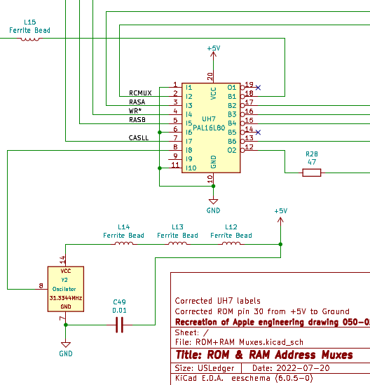
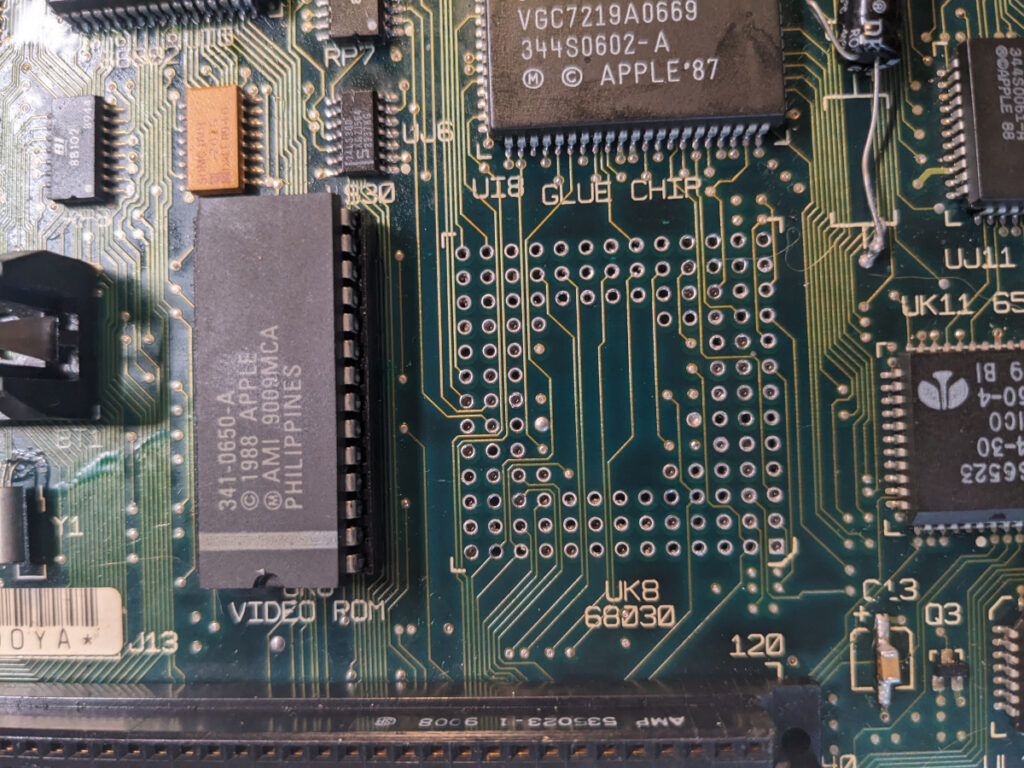
So how does the SE/30 generate video sync? Since we’re dealing with analog video, we need a horizontal and vertical sync. We start from the Y2 32Mhz oscillator. This is the main crystal that is also used for the 68030s 16Mhz clock. Y2 provides 32Mhz to the UH7 PAL. This PAL then passes that signal onto both the UI8 GLUE chip and the UI6 PAL as C32M. The GLUE chip splits it in half to 16Mhz and passes it to UI16 as C16G, which then passes it onwards as C16M. Then additional video logic PALs, in conjunction with LS393 binary counters, generate VSYNC and HSYNC signals (UG7 for HSYNC and UG6 for VSYNC).
This, roughly, is all the logic needed to generate video sync signal (there’s lots more passive components necessary). Without adding anything else, you could get an image like this on the CRT:
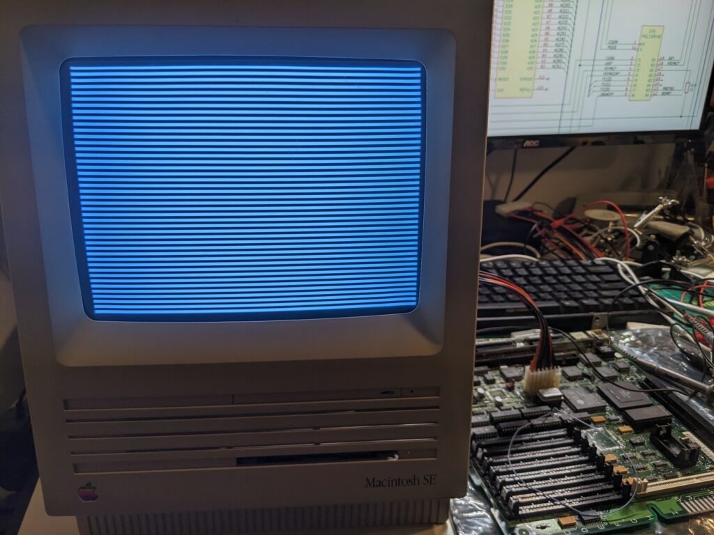
If you add the video RAM, 74LS166 shift register and the remaining PAL chips, you’ll get the jail bar pattern (with the particular video RAM I am using. Other types may give other simasimac patterns):
What I observed on board #3, as well as the other two boards, was that the video sync signal starts to break after a while, resulting in the collapsing image symptom. It will start with VSYNC and eventually collapse HSYNC as well. At this point I suspected a bad component — perhaps it was the oscillator?
I replaced the oscillator.
Perhaps one of the PAL chips?
I replaced the PAL chips.
Perhaps the GLUE chip?
I couldn’t replace the GLUE chip since it’s a custom chip that hasn’t been reverse engineered yet. But going back to the video sync generation logic, we see that the only use of the GLUE chip for generating the signal is to divide 32Mhz in two. I could do that without it.
So I built myself a frequency divider, and programmed a 20 pin F16V8B GAL instead of the UH7.
Same. Damn. Thing.
I was hitting the same wall again and again and again.
Power theories
For a while I even suspected the power supply. I had the same issue in my SE chassis, and my SE board would work fine in the SE/30 chassis. I even wired up an ATX power supply. I recapped the analog board.
Someone suggested my electrical wiring at home might be bad (!). I didn’t really think that could be the case since the building is less than 5 years old, but sure. I ran the power supply off of a UPS.
Same. Damn. Thing.
Giving up
This was going nowhere. I somehow replicated the same issue on a brand new board, and considering the shorts, it was unlikely this thing was going to be recoverable. By this point I spent literally countless hours and quite a bit of money on this project, and I was actually in a much worse place than when I brought the damn thing home. I was disappointed, and the worst thing was, I felt like I didn’t even learn anything.
At this point while folks were still encouraging me to continue, I really felt like giving up. Helpful people shared advice, but we were past the point where this could be troubleshot remotely.
One thing that kept coming back was the idea that there was a short somewhere. But I couldn’t detect it. The fact that there is relatively small resistance between ground and 5V on a good SE/30 board made this difficult to prove.
I left this for a few weeks. Eventually, I made a decision I would give it one, final try.
Regrouping
I ordered a set of brand new reloaded boards.
JLCPCB has a minimum of 5. The cost was more than I paid for the SE/30 and the two boards in the first place ($150 with shipping). At this point this was either going to work, or not. I would use these boards to experiment, to finally crack how this thing works. It wasn’t about getting a functioning SE/30 anymore — it was about getting a small set of electrical components to behave well enough not to collapse.
Boards #4 and #5
I was patient, and precise. Slow and methodical. No unnecessary components. Minimum viable circuit. Despite some early stability, two times I tried again, and two times I failed. Boards #4 and #5 were doing the same thing as all the other ones.
I stepped away again. I thought about everything that’s gone into this. I couldn’t shake the feeling that I was somehow infecting these boards with this issue. There was barely anything common between them. Yes, I reused the GLUE chip, but I also got the same stuff with my own clock divider. Something else was causing this. Something else was the pattern.
Oh.

This was such a relief. I didn’t yet know what the actual problem was, but it made sense. A total of five logic boards, same symptom. I replaced everything else, other than the person doing the work. It should have been obvious earlier on, but the one factor I did not control was the actual work being done to solder different components onto these boards. It was me – I was the pattern.
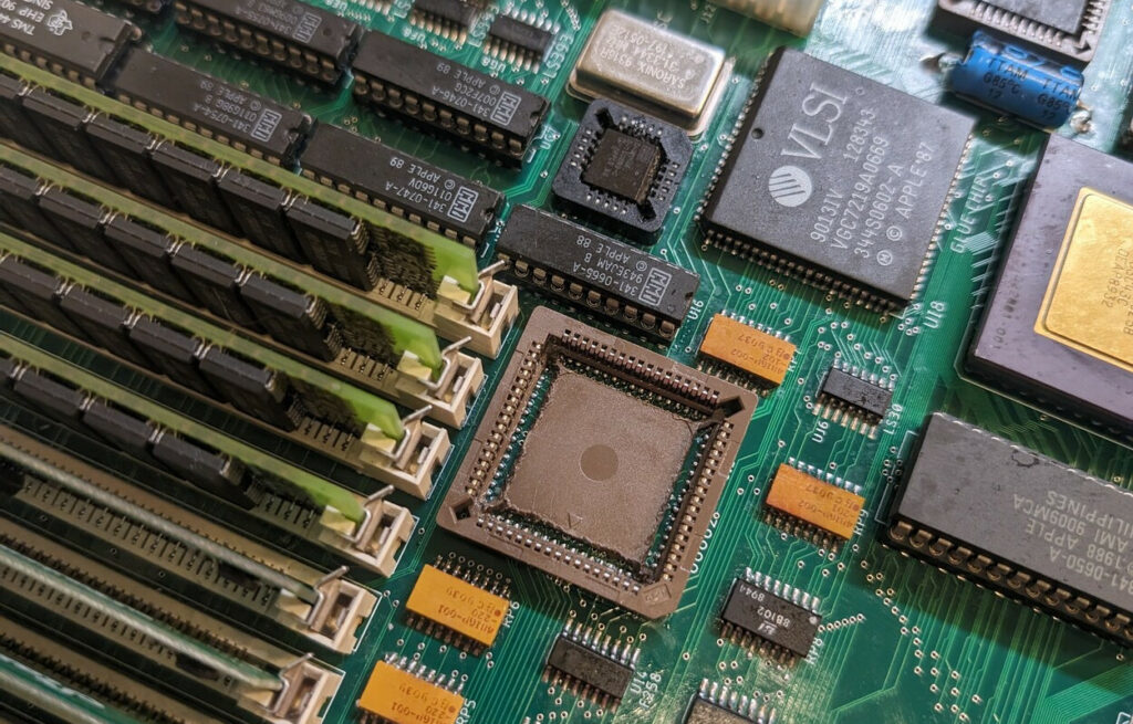
I took another break for the month of December. I traveled and decided I would continue in the new year. I had 3 boards left, and if I couldn’t get it right with those, I would pass this chunk of SE/30 parts to someone who can. I thought about what I could be doing wrong, and the only thing that came to mind was the soldering of tight SMD chips. This all started with me removing the GLUE chip on board #2, and even for the minimum viable video sync circuit I had to at least install UH7. So let’s talk about UH7 for a second…
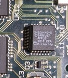
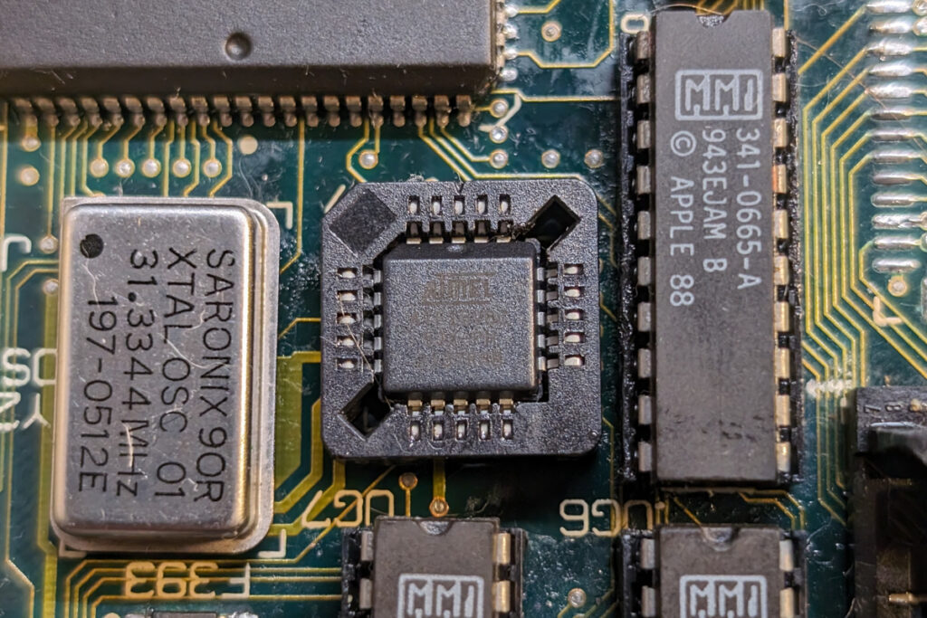
UH7 passes on 32Mhz clock signal from the oscillator. It’s also the only PAL logic chip that’s in PLCC-20 instead of DIP-20 form. It’s located in between the oscillator, the GLUE chip and other PAL logic. It’s hard to access. And it’s pads can barely be accessed with a soldering iron. It’s tough to solder.
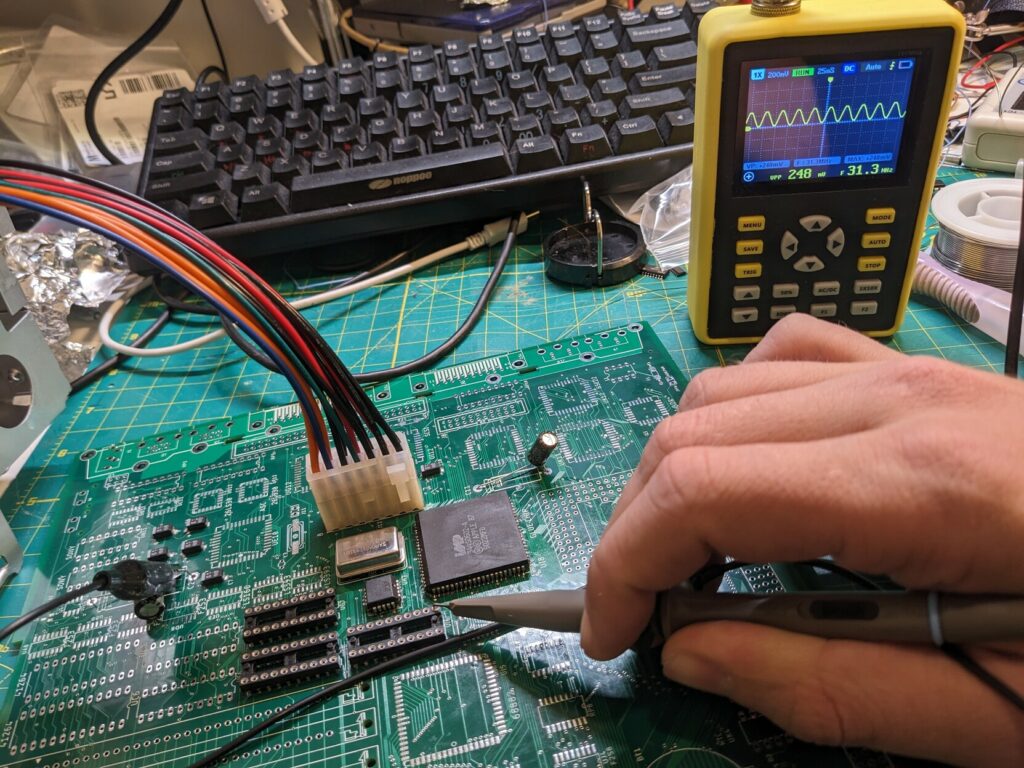
Epiphanies
Even when I replaced the chip, as in the image above where I’m using an ATF16V8C, I would have to solder it on. What could I do to ensure my soldering wasn’t making tiny shorts? A friend mentioned that I should try to use sockets — they might be easier to solder, and I would be able to test different components more easily. I initially decided against SMD sockets because of concerns that they would cause contact problems (this may be foreshadowing something later). But I had much bigger issues. In early January I got some PLCC sockets, and decided to test it on board #2, the original sort-of-good board, by placing the socket on UH7.
Also, I got new flux (remember this for later).
Guess what? The image did not collapse. I ran it for 90 minutes, with the sad jail pattern, and the image did not collapse.
I’m the problem, it’s me.
This board obviously still had problems preventing it from booting. After all the work I’ve done, I suspected there may have been broken connections inside the board. I decided to go for one more rebuild, this time with sockets, and with a full arsenal of parts — I would use board #2 as donor as well. It was all or nothing.
Board #6 – The board that boots
I was patient. I was precise. I socketed everything. Yet, I would lie if I said this board booted immediately. However, it never collapsed, and it was showing signs that it’s trying to do something. At this point I tried to be as analytical as possible in my troubleshooting, precisely understanding what the board does in different conditions. Techknight from 68kmla.org was very helpful with his SE/30 videos, especially the one where he demonstrated how the 68030 walks the memory bus when no ROM is installed:
On January 20th I finally got a successful boot.
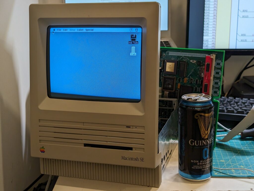
It was a matter of identifying functioning parts and (as I would later learn) getting them to fit in sockets just right to get them to work.
I was ecstatic! Approximately 120 days after I brought this SE/30 home it was finally fully working. In the last stretch I even got a replacement 68030 (something that later on proved to be unnecessary), but it didn’t matter. This computer Worked.
I proceeded to experiment and play with it for a few weeks afterwards. It was, after all, well earned.
But, it was not the end…
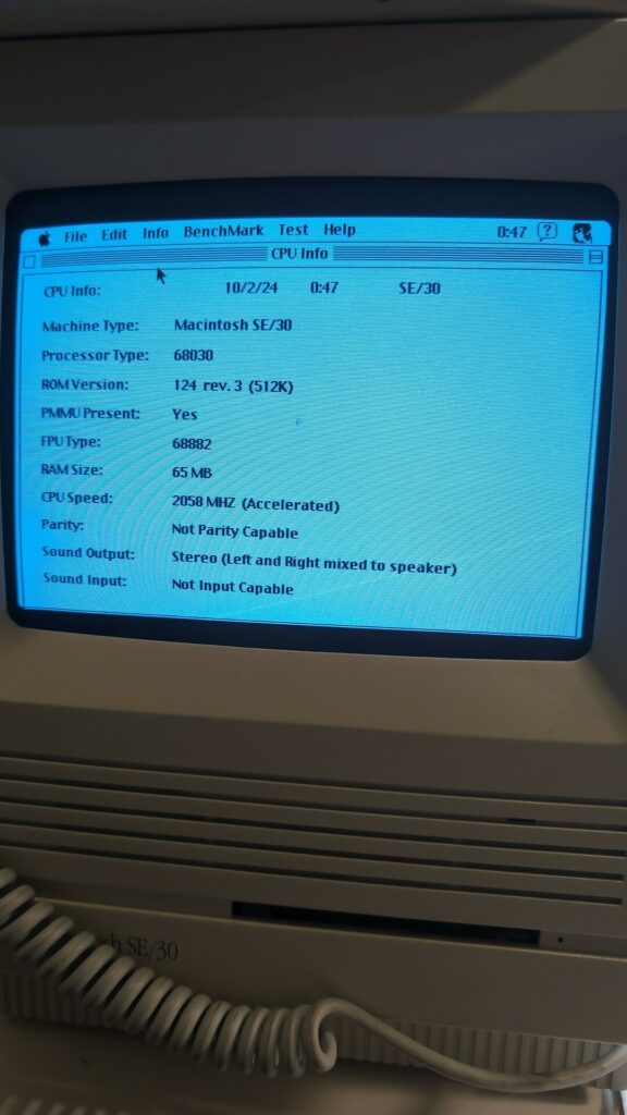
The revenge of the sockets
A few weeks later, I decided to build board #7. At this point I knew I could do it, and I had enough parts for another one. I didn’t hurry too much, but I did switch chips between the two. While still working on board #7, I started to notice strange issue with board #6 (uh-oh). It suddenly started randomly crashing and reporting CPU and FPU issues in Snooper. Checking the machine info showed a strange 2058 Mhz speed which was obviously incorrect.
Soon the FPU stopped being reported at all, and any application needing to use the FPU would fail with Error Type 1. I tried booting without an FPU (since I have a Rominator which can boot without it) and I would get Error Type 90 (i.e. “an FPU instruction was executed but the machine doesn’t have an FPU”). I also had SCSI trouble, and floppy trouble. What was happening? Was I infecting my machines, again?
I had 3 FPUs, and none of them worked. I got another one, and the same thing happened. It must have been the sockets. Like UH7, FPU is tricky to solder because it’s surrounded by plastic components and the pads are very tight. I hesitated to solder the FPU directly without knowing whether it was good. I decided to go with a new socket, but I left the plastic bottom in place (previously I had cut it out). It made it somewhat difficult to solder in the corners, but luckily the FPU showed up correctly in the system immediately after installation.
I also went ahead and soldered the GLUE and SCSI chips directly, resolving their respective issues. After all the help from the sockets, they came back to bite me. Speaking of getting bitten…
Board #7 – The one that confirmed the problems
In February I decided to build board #7, ie. second new board that would work. The build was uneventful, until I ran out of flux. I wanted to keep going, so I dipped into my old jar of flux.
Guess what happened?
Yes, the sockets probably helped, but I can safely say now, my issue with the collapsing image was initially, and subsequently primarily caused by this stuff:
I now know that rosin flux can be conductive at certain temperatures. It makes sense that it would cause shorts that would take a few minutes to show up, as it heats up. In retrospect, I believe that this thing probably caused similarly bizarre issues with a BlueSCSI I assembled a few years ago. Yes, I should have been better about cleaning it up, but this stuff ended up in the trash and I’m never using it again.
After a thorough clean in IPA, washing, another round of IPA, washing and cleaning, and drying of course, board #7 would not collapse, proving once and for all that shorts were the cause of the issue, and my rosin flux was the likely culprit all along.
Getting board #7 fully working took some more work. Sockets ended up being an issue again — I ended up soldering SCSI, GLUE and UK11 (one of the VIA chips). I replaced the FPU socket for one with a plastic bottom because the FPU again wouldn’t get recognized. I even had to replace the socket for the video ROM because the cheap socket I had in there wouldn’t make good contacts with the ROM! This one was weird to troubleshoot and eventually I figured it out by seeing the computer boot from SCSI by its blinking lights when the video ROM was be taken out. It must have been messing with the bus. All in all, board #7 took about 3 weeks from start to fully functional.
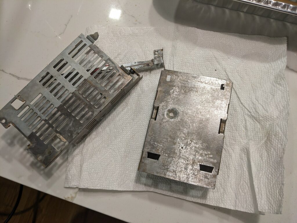
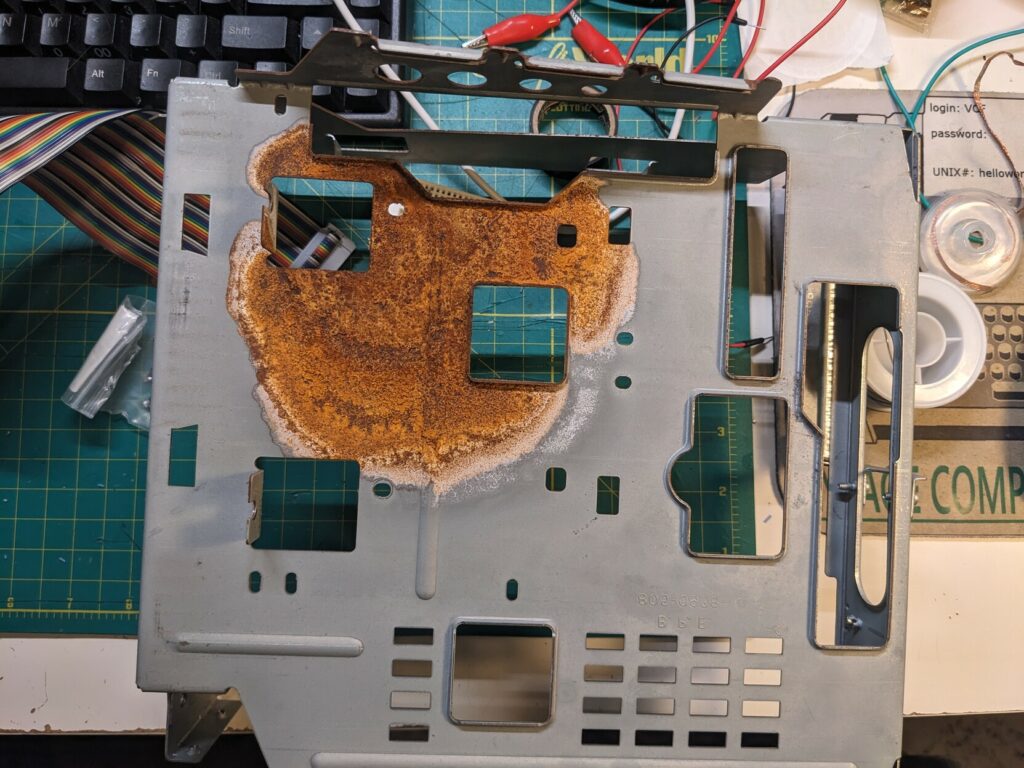
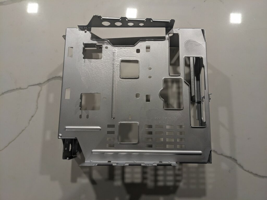
Chassis rust removal work
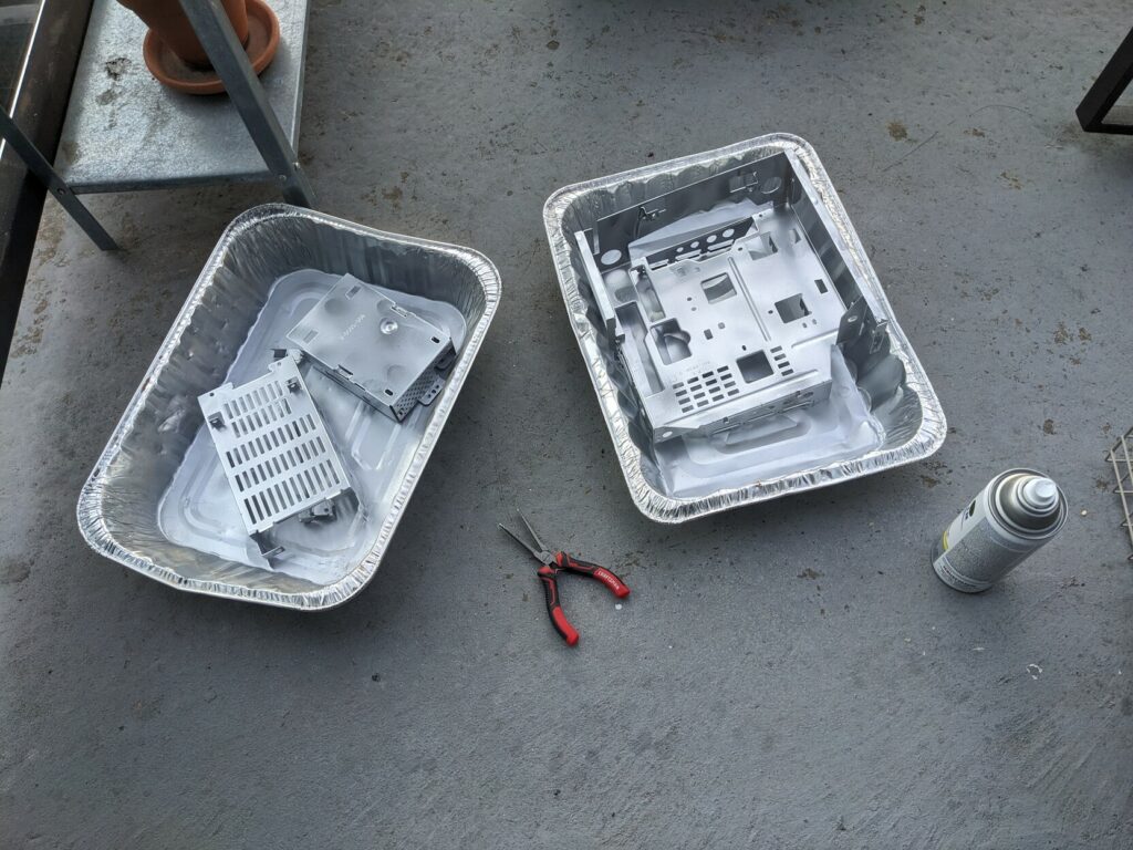
Sometime in the fall I spent a few days working on the badly rusted chassis that was damaged by the battery explosion. I started by giving it a vinegar bath.
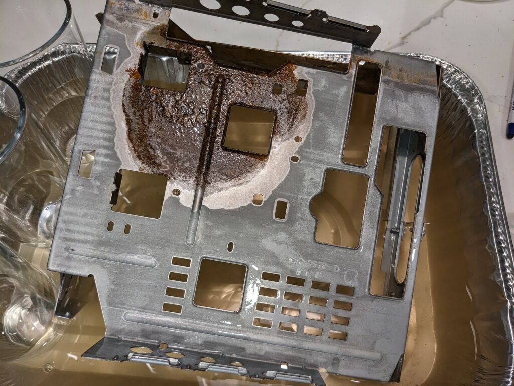
After a while, the vinegar cleaned it up really well, but the metal still stained with very thin layer of rust:
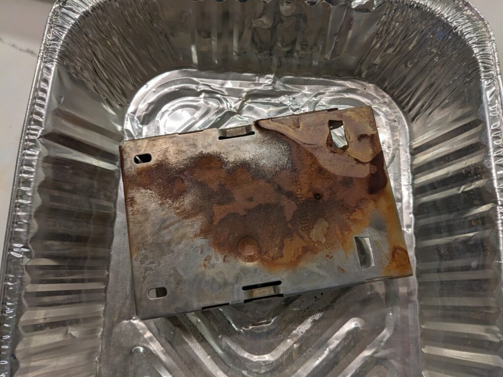
This was very annoying. I went through a couple of rounds of vinegar baths until I realized that there was no way I would get all the rust off that way. Moreover, the stains would appear on the parts of the metal that had no rust in the first place! I decided to remove the rust with a dremel and steel wool.
Finally, I applied a few coats of Rustoleum spray. The color is close to the original, but note that this paint is not conductive so I made sure the points of contact with the logic board and screws were scratched enough to make contact.
Before and after:
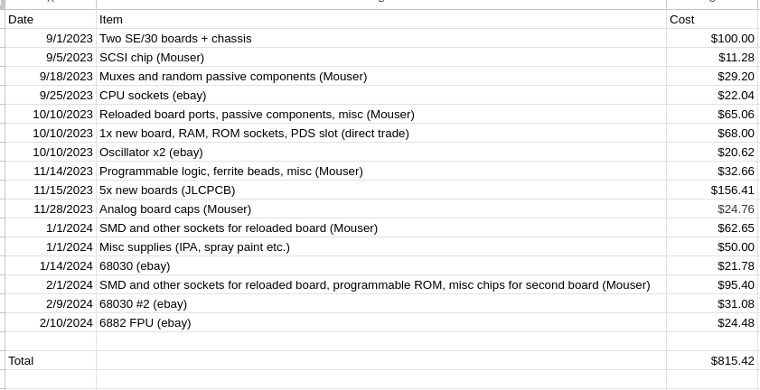
Cost
I hesitated whether to calculate the cost of this project. This work is clearly irrational outside the very particular context of a weird hobby. While I did not want to buy an overpriced SE/30 on principle, I spent A LOT more money on getting one complete SE/30 and an extra board than I would have if I just bought an overpriced SE/30 in the first place. But, I think it is interesting and useful to share this information transparently like this. Note that this does not include any of the new tools I bought (like the hot air station) nor additional hardware like new RAM, Rominator II and BlueSCSI V2 — I only counted the items I needed to actually get these boards working.
I wouldn’t want to speculate the cost in my time as it would be more upsetting than the collapsing image issue itself. I did learn something in the end, so let’s leave it at that.
Final notes
This project got so blown out of proportion in time, effort and money that it is really difficult to assess whether it was worth it. It challenged me by an order of magnitude more than any electronics project I’ve tackled to date, and I can say that I learned a lot. I could probably rebuild an SE/30 in less than 2 weeks now. I probably won’t, though — this is a hobby for me, and I’ve successfully figured this one out — it’s time for something new. We’ll see what comes next.
I wanted to share some resources that I found indispensable working on this project:
- mishimasensei’s SE/30 schematic recreation
- Original SE/30 schematic
- Bolle’s logic PAL dumps and the whole SE/30 logic board recreation project
- THEtechknight’s videos and posts on 68kmla.org
- Branchus Creations videos
- JDW’s recommendation to use an ATX extension cable to work with your logic board outside the case
- 68kmla.org forums
- TinkerDifferent forums
- Encouragement, tips and comments from many folks!
Repairing old electronics is fascinating. For a discipline that is based on digital logic and the concept of binary states, it’s fascinating how much of working with this technology is almost esoteric. I really appreciate the importance of experience and craft after completing this project. It really was a matter of skill and experience that made a difference in finally bringing this one to a close. Thanks for reading!